


DAV101CM, DAS101CM • Quick Start Guide
iii
Quick Start — DAV/DAS101CM Series
C
Installation and service must be performed by authorized
personnel only. These units must be installed in
accordance with national and local electrical codes.
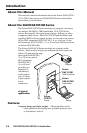
To install the DAV101CM and DAS101CM modules, see the
appropriate section of this manual and follow these steps:
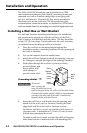
Step 1
Install an electrical box or wall bracket (if applicable) and cables.
Use cable clamps to hold cables in place for strain relief. Trim back
or insulate exposed cable shields with heat shrink to prevent short
circuits. See pages 2-2 to 2-3.
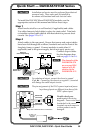
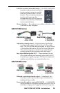
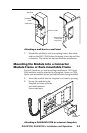
Step 2
Attach cables to the rear panel. Ensure that power and output cables
have been fed through the wallbox/furniture and out the front of the
faceplate, frame, or panel. Connect modules to each other (if
applicable) and to the power supply, but do not apply power yet.
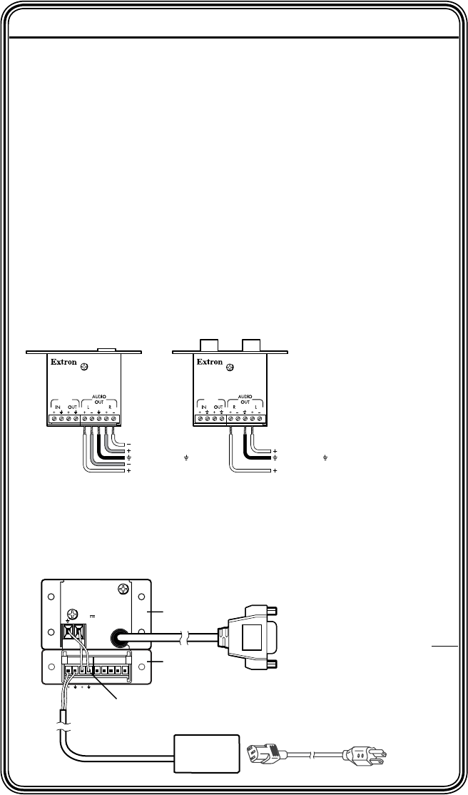
Connect output cables.
See the diagrams here
and on pages 2-4 to 2-6.
C
For unbalanced output, connect the sleeve to ground
(Gnd,
_
). Connecting the sleeve to a negative (-) terminal
will damage the audio output circuits.
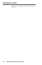
C
The pin assignments of the DAS’s power input and power
loop-through ports are different from those of the
DAV’s power input.
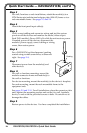
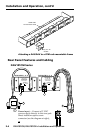
Double-check your
work against the wiring
diagrams. Power wires must
be attached to the correct
terminals on each connector
or these products can be
damaged.
DAS101CM-1/-2/-5
Bottom View
DAS101CM-3/-4/-6
Balanced
Stereo Output Wiring
Unbalanced
Stereo Output Wiring
12
VDC
0.1 A
12
VDC
0.1 A
Right, tip, +
Left, tip, +
Ground, sleeve(s),
Gnd, sleeve(s),
Left, ring, –
See caution.
Left, tip, +
See caution.
Right, ring, –
Right, tip, +
N
The channels of the
DAS101CM-3/-4
are reversed (R-L
instead of L-R)
relative to the
DAS101CM-1/-2.
+
TECHNICAL SUPPORT:
800.633.9876
714.491.1500
www.extron.com
MADE IN USA
POWER IN
12V @0.3A
DAV101CM
(back view)
12 VDC, 1 A
DC Power
Adapter
OUTIN
DAS101CM
(back view)
Power In
Loop Out to DAV101CM or CIA Interface
Quick Start