


DMS 1600, DMS 2000, DMS 3200, DMS 3600 • Installation 54 DMS 1600, DMS 2000, DMS 3200, DMS 3600 • Introduction
Installation
This section describes installation of the DMS matrix switchers, including
connections and features. Topics that are covered include:
• Rear Panel
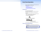
• Front Panel
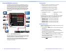
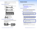
Rear Panel
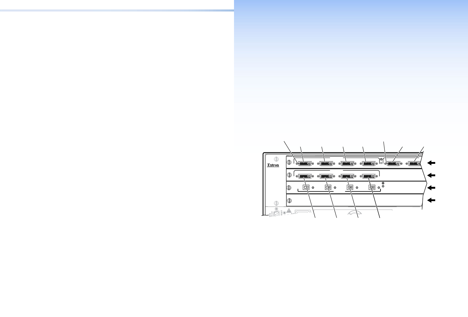
I/O Board Configuration Overview
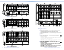
See gure 2. Each I/O board is identied by the input and output
connector numbers supported by the board position. The input and
output numbers on the boards are identied as locations A through D.
ANAHEIM, CA
100-240V 50/60Hz 1.2A MAX.
PRIMARY POWER SUPPLY
1 - 4
5 - 8
9 - 12
13 - 16
DVI-D INPUTS
A B
DVI-D INPUTS DV
C D
ABCD
A B
AB
TMDS
FIBER
INPUTS
CD
Slot
1
(1-4)
Input 1
Slot
2
(5-8)
Slot
3
(9-12)
Slot
4
No board
installed
Output 1Input 3 Input 4Input 2 Output 2
Input 5 Input 6 Input 7Input 8
Location A
Input
Location A
Output
Figure 2. Arrangement of Inputs and Outputs on the I/O boards
The board position designators correspond to the input and output
numbers served by that position (1 through 4, 5 through 8, and so on).
The location designators, A through D, correspond to the DVI input or
output, grouped with inputs on the left and outputs on the right and
numbered from left to right.
The input numbers supported by the I/O board in slot 2 (locations
5 through 8) are as follows: A = 5, B = 6, C = 7, D = 8.