


8 DMS 1600, DMS 2000, DMS 3200, DMS 3600 • Installation 9DMS 1600, DMS 2000, DMS 3200, DMS 3600 • Installation
e
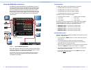
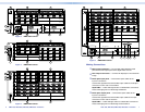
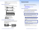
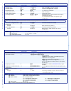
Remote port — If desired, connect a control system or computer to
the rear panel Remote RS-232/RS-422 port.
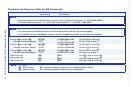
RS-232 Function Pin Function
1
2
3
4
5
6
7
8
9
—
Tx
Rx
—
Gnd
—
—
—
—
Not used
Transmit
Receive
Not used
Ground
Not used
Not used
Not used
Not used
—
Tx–
Rx–
—
Gnd
—
Rx+
Tx+
—
Not used
Transmit (–)
Receive (–)
Not used
Ground
Not used
Receive (+)
Transmit (+)
Not used
RS-422
5
1
96
Figure 7. Remote RS-232/RS-422 Output Connector Wiring
f
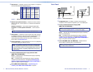
Ethernet port (LAN connector) — If desired, connect a network
WAN or LAN hub, a control system, or a computer to the Ethernet
RJ-45 port.
Network connection — Use a patch (straight-through) cable.
Computer or control system connection — Use a crossover
cable.
NOTE: The factory default IP address is 192.168.254.254.
g
Reset button — Initiates four levels of reset of the matrix switcher.
For different reset levels, press and hold the recessed button while
the switcher is running or while you power up the switcher.
See the DMS Series Matrix Switcher User Guide, available on the
Extron DVD or at www.extron.com.
h
Power connectors — Plug the switcher into one or two (depending
on the DMS model) grounded AC sources.
NOTE: For reliability in switchers with Primary and Redundant
power supplies, connect the power cord from the Redundant
power connector to either an uninterruptible power source or to
a power source that is completely independent of the primary
power source.
i
Primary and Redundant power supply indicator LEDs
(DMS 1600 and DMS 3600) —
Green — Indicates that the associated power supply is operating
within normal tolerances.
Red — Indicates that the associated power supply is operating
outside the normal tolerances or has failed (see Removing and
Installing a Power Supply Module (DMS 1600 and DMS 3600) on
page 31 to replace the power supply).
j
Fans (DMS 1600 and DMS 3600) — See Removing and
Installing a Fan (DMS 1600 and DMS 3600) on page 32.
Front Panel
DMS 1600
TMDS DIGITAL MATRIX SWITCHER
POWER SUPPLY
PRIMARY
REDUNDANT
CONTROL
ENTER PRESET
VIEW
ESC
CONFIG
CONTROL
DMS 2000
TMDS DIGITAL MATRIX SWITCHER
CONFIG
POWER
ENTER PRESET
VIEW
ESC
1 3
1 2
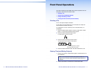
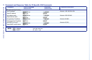
Figure 8. Front Panel Features
a
Configuration port — If desired, connect a control system or
computer to the front panel Conguration port, a mini USB B port
.
b
Primary and Redundant Power Supply LEDs
(DMS 1600 and DMS 3600) —
NOTE: The meaning of these indicators is identical to the LEDs
on the power supplies (item
i
, on the previous page).
Green — Indicates that the associated power supply is operating
within normal tolerances.
Red — Indicates that the associated power supply is operating
outside the normal tolerances or has failed (see Removing and
Installing a Power Supply Module (DMS 1600 and DMS 3600) on
page 31 to replace the power supply).
c
Power LED (DMS 2000 and DMS 3200)— Indicates that the
power supply is operating within normal tolerances.
NOTE: The power supply is fixed, and not field replaceable, on
the DMS 2000 and DMS 3200.