


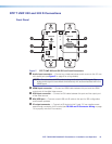

DTP T HWP/UWP 232/332 D Transmitters • Installation and Operation 5
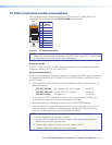
Site Preparation and Wall Box Installation
Choose a location that allows cable runs without interference. Allow enough depth for both
the wall box and the cables. Install the cables into the wall, furniture, or conduits before
installing the wall plate.
NOTE: The extender units are very deep and have connectors on the back side. Extron
recommends a 2-gang wall box which has a depth of at least 3.0 inches (7.6 cm) to
accommodate the connectors and cables.
To install a new wall box, perform steps 1 through 9. If a suitable wall box is already
installed, perform steps 6 through 9 on the next page. UL Listed wall boxes are
recommended.
1. If a wall box is not available to use for a template, use the Decora Template
Dimensions on page 24 to create a template. If installing directly into furniture, cut out
the center portion of the template.
2. Place the wall box (or the full size template) against the installation surface, and mark
the opening guidelines.
3. Cut out the material from the marked area.
4. Insert the wall box into the opening. The rear connectors on the box or wall plate should
fit easily into the opening. Enlarge or smooth the edges of the opening if needed.
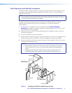
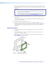
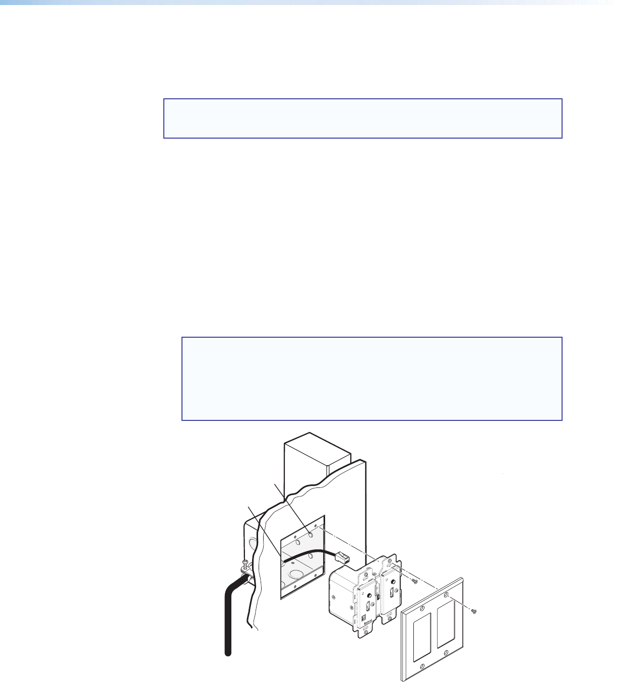
5. Secure the wall box with nails or screws, leaving the front edge flush with the outer wall
or furniture surface (see figure 2).
NOTES:
• If attaching the wall box to wood, use four #8 or #10 screws or 10-penny
nails. A minimum of 0.5 inch (1.3 cm) of screw thread must penetrate the
wood.
• If attaching the wall box to metal studs or furniture, use four #8 or #10
self-tapping sheet metal screws or machine bolts with matching nuts.
Signal Output
Cable
Cable
Clamp
Decora Faceplate
Extron
DTP UWP 232 D
Extron
DTP HWP 232 D
Screws or
Nails
Wa
ll opening is
flush with edge of box.
Wall Stud
Signal Output
Cable
Cable
Clamp
Decora Faceplate
Screws or
Nails
Wall opening is
flush with edge of box.
Wall Stud
AUTO SW
CONFIG
IR OUT
HDMI IN
AUDIO IN
S
G
HDMI IN
AUDIO IN
HDCP
1
AUTO SW
CONFIG
IR
OUT
HDMI IN
AUDIO IN
S
G
HDCP
1
AUDIO IN
VGA IN
Figure 2. Installing the Wall Box and Mounting the Unit