


DTP T HWP/UWP 232/332 D Transmitters • Installation and Operation 11
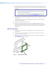
Rear Panel
R
DTP OUTREMOTEOVER
DTP
SIG LINK
RS-232
CONTACT
Tx Rx
Tx Rx G
POWER
12V
A MAX
0.9
+–
G12
A/S
DTP T HWP/UWP 232/332 D
Rear Panel
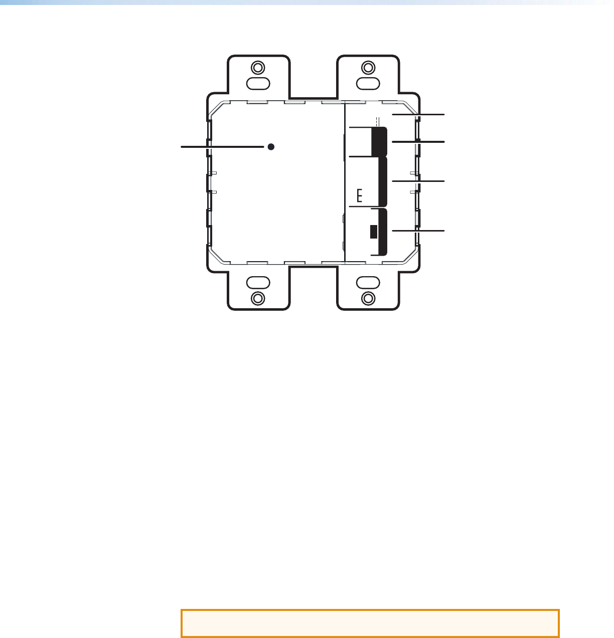
E
A
B
C
D
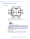
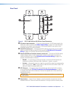
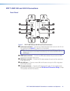
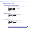
Figure 8. DTP T UWP 232 and 332 D Rear Panel Connectors
A DC power input connector — Plug the included external 12 VDC power supply into
either this 2-pole connector (see Power supply wiring on page 13 to wire the power
connector) or the power input connector on the receiver (see the User Guide of your
respective receiver for more information).
B Over DTP control port — Connect an RS-232 device to this 3-pole, 3.5 mm captive
screw connector for pass-through RS-232 control (see RS-232 and IR Connector
Wiring on page 14 to properly wire the RS-232 connector).
C Remote (RS-232 and contact closure) control port — Connect an RS-232 device,
contact closure device, or both to this 5-pole, 3.5 mm captive screw connector to
control switching on the unit (see RS-232 and IR Connector Wiring on page 14 to
properly wire the Remote connector).
• RS-232 — To control the unit through this port, connect an RS-232 device and
configure it as follows: 9600 baud rate, 8 data bits, 1 stop bit, no parity.
• Contact — Momentarily short pins 1 or 2 to ground (G) to select the corresponding
input. Connect pins 1 and 2 to ground (G) to set the unit to auto switch mode. The
device will select the highest active input.
D DTP Out port — Connect one end of the twisted pair cable to the RJ-45 connector
on the transmitter (see TP Cable Termination and Recommendations on page 12
to properly wire the RJ-45 connectors). Connect the opposite end of the cable to the
appropriate receiver.
ATTENTION: Do not connect this device to a telecommunications or computer
data network.
E Reset button — Use an Extron Tweeker or small screwdriver to press and hold the
recessed button for 6 seconds while the extender is running to perform a factory reset.