


HSA 400/402 Series • Installation
HSA 400/402 Series • Installation
Installation, cont’d
2-10
HSA 402
H. SHIFT
COMPUTER
INPUT
SELECT
AUDIO
RGB 580
xi
SI AAP
120-240 50/60 Hz 5A 120-240 50/60 Hz 5A
3
1A 1B 1C
2
1D
Underside View
Front Panel View
1A 1B 1C 1D
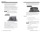
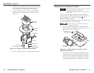
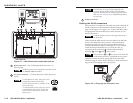
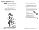
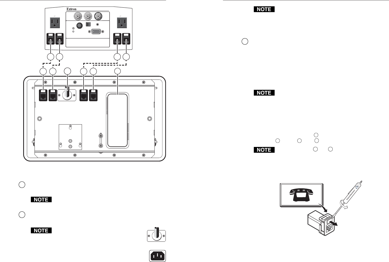
Figure 2-7 — HSA 402 enclosure underside features
1
RJ-45 connectors — See “Cabling the RJ-45 connectors” on
the next page.
All RJ-45 connectors are teminated in accordance with
the TIA/EIA T 568 A standard.
2
AC power connector — Connect this power cord to the power
source.
For US domestic versions, this power cord is
permanently connected to the HSA.
Connect the power cord to a 125VAC, 60 Hz,
10A power source.
For international versions, this power cord is
a removable IEC power cord. Connect the
power cord to a 220-250V, 50-60 Hz, 10A
power source.
The Universal AC outlet is fully compatible with
Europlug, British, Indian, Danish, and Italian plug
types. See the universal AC outlet guide on the Extron
Web site, www.extron.com, for compatibility details on
all plug types.
3
Cable access holes
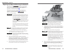
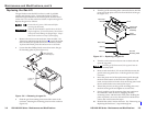
Cabling the RJ-45 connectors
Plug one end of a twisted pair (TP) cable into each of these RJ-45
female connectors on the underside of the HSA (figure 2-6 on
page 2-9 and figure 2-7 on page 2-10). Connect the other end to
an appropriate telecommunications or data network or to an
Extron TP product.
An RJ-11 (telephone) jack can be plugged directly into
the RJ-45 jack.
Cables inside the HSA route the network cables from the front
panel to the underside of the enclosure. The bottom RJ-45
connections match up with the front panel RJ-45 connector
locations identified on figure 2-6 and figure 2-7. For example,
match the front panel RJ-45 (CAT 5/6) network, data, or
communications connection
1A
with the underside RJ-45
connector
1A
, match
1B
with
1B
, and so forth.
Only connectors
1A
and
1B
are present on the HSA 400.
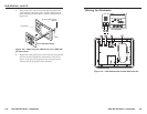
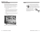
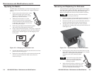
If necessary, on the front panel, have a qualified service person
replace the connector icon by prying the old icon off of the
connector plug-in with an Extron Tweeker or small screwdriver
(figure 2-8) and snapping a new icon in place.
Icon Label
Figure 2-8 — Changing the connector icon
2-11