


HSA 400/402 Series • Maintenance and Modifications
HSA 400/402 Series • Maintenance and Modifications
Maintenance and Modifications, cont’d
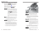
CAUTION
The flanged edges of the top of the surface enclosure
are bevelled to an ultra-fine thickness of less than
0.04 (4/100)" (approximately 1 mm). These edges
are soft and can be easily nicked or bent. Exercise
caution when handling and mounting the enclosure.
Mishandling can damage the appearance of the
enclosure.
The surfaces of the HSA enclosure have screws and
other protrusions that could damage fine furniture.
Do not rest the enclosure on unprotected furniture.
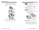
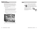
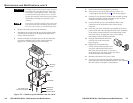
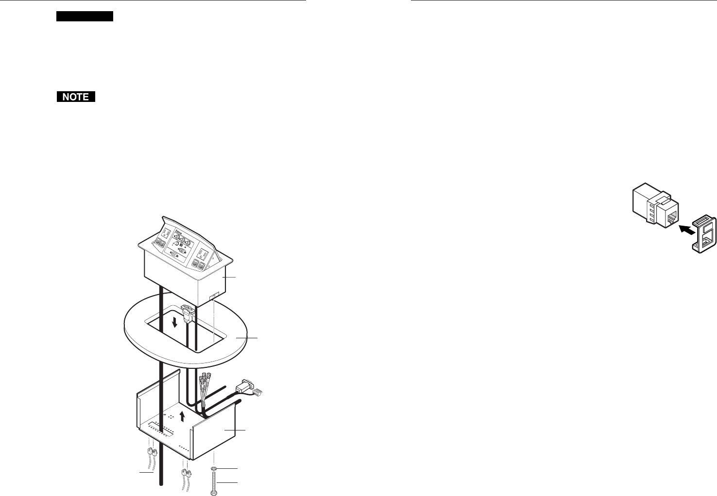
6. Remove the front panel from the enclosure.
7. Disconnect any cables from the rear of the existing AAPs.
Carefully pull the cables out through the bottom of the
surface mount enclosure.
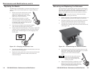
8. On the underside of the table, remove the two bolts that
secure the clamshell to the surface mount enclosure
(figure 3-5). Lift the enclosure out of the table.
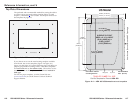
AAP Cables
H. SHIFT
COMPUTER
INPUT
SELECT
AUDIO
R
G
B
5
80
x
i
S
I A
A
P
HSA 402
Mounting
Surface
125 - 50/60 H
z 5A
125 - 50
/60 Hz 5A
Full Thread
Mounting Bolts
Flat Washer
IEC Power Cord
4 RJ-45 Connectors
HSA 402
Clamshell
Figure 3-5 — Removing the HSA 402 from the table
3-73-6
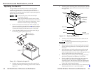
9. Perform the desired maintenance procedure.
10. If the surface is not level, adjust the top surface. See
“Adjusting the Top Surface Level”, later in this chapter.
11. Carefully lower the HSA enclosure into the table opening.
From the underside, bolt the clamshell to the enclosure
with the two bolts removed in step 8.
12. Connect the IEC power cord and RJ-45 cables to the
connectors on the underside of the surface mount
enclosure.
13. Cable the rear of the AAPs that are installed on the front
panel. Route the cables through the hole in the underside
of the surface mount enclosure and connect them to the
rear of the AAPs. If applicable, refer to the cabling
information in the AAP documentation.
14. Snap the interior RJ-45 connectors
onto the rear of the front panel
bezel plug-ins.
15. Replace the front panel in the
surface mount enclosure and secure
it in place with the hex head screws
that were removed in step 4. If you lose a
front panel screw, two spare screws are stored
in the underside of the clamshell.
16. Reconnect the interior AC power cable.
17. To prevent wear and tear caused by cable movement,
secure the AAP cables underneath the table. See “Routing
the AAP Cables” in chapter 2, “Installation”.