


HSA 400/402 Series • Installation
HSA 400/402 Series • Installation
Installation
2-3
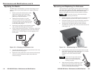
Preparing the Routing Template
Extron offers a metal template for each HSA model.
Appendix A lists the HSA 400/402 template part numbers.
Extron recommends using this template as a guide to cut the
hole in the table where the HSA will be installed.
The metal routing template is reusable. Do not discard
this template when the installation is complete. Save it
for installing future HSA enclosures of the same size.
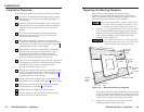
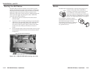
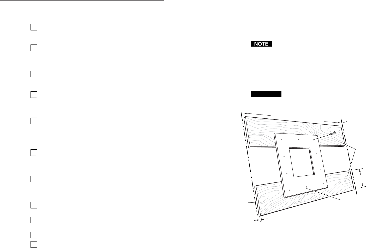
1. Cut two 1/2" x 4" (approximately 13 mm x 102 mm) strips
of soft, finished lumber at least long enough to span the
distance between the desired installation location on the
table or other mounting surface and the edges of the
mounting surface (figure 2-1).
CAUTION
Do not allow the wood screws to protrude through
the bottom of the wooden strips. Protruding screws
will mar the table when the template is used.
Mounting
Surface
Edge
Mounting
Surface
Edge
Wood Thickness
0.5" / 1.3 cm
Width of Mounting Surface
Routing Template
Wood Strip
Height
4" / 10.2 cm
Minimum
4 Screws
Wood
Strips
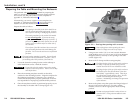
Figure 2-1 — Prepared mounting template
These strips raise the routing template above the mounting
surface to provide room for the router’s collar, protect the
mounting surface, and extend the routing template’s reach
so that it can be clamped to the edge of the surface.
2. Using four or more short wood screws, secure the
mounting template to the lumber strips.
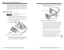
Installation Overview
Install and set up the HSA surface access enclosure as follows:
1
If you have an unprepared mounting template, prepare
the template. See “Preparing the Routing Template” on
the next page.
2
If desired, install the optional RJ-45 to RJ-11 conversion
kit(s) to replace one or more RJ-45 connectors with RJ-11
connectors. Refer to the RJ-45 to RJ-11 Conversion Kit
manual.
3
If desired, install the optional flexible conduit kit to
replace the removable AC power cord. Refer to the
Flexible Conduit Kit manual.
4
Cut a hole in the surface where the enclosure will be
installed and install the enclosure. The clamshell clamps
the enclosure to the table. See “Preparing the Table and
Mounting the Enclosure” in this chapter.
5
Run all cables necessary to support the AC and RJ-45
connectors and all planned AAP connectors. Leave
enough slack in the cables to connect them to the
underside of the enclosure or to the rear of the AAPs
before the AAPs are installed in the enclosure.
6
Turn off all of the equipment to be connected. Ensure that
the equipment connected to the RJ-45 connectors and the
connections for any AAPs are all turned off and
disconnected from the power source.
7
If applicable, connect cables to the rear connectors on the
AAPs to be installed in the HSA. Install the desired AAPs
on the front panel of the enclosure. See “Cabling and
Installing the AAPs” in this chapter.
8
Connect the power and RJ-45 cables to the underside of
the enclosure. See “Cabling the Enclosure” in this chapter.
9
Route and secure the AAP cables inside the clamshell.
See “Routing the AAP Cables” in this chapter.
10
Peel the protective coating from the top surface.
11
Connect the power cords and turn on the devices that
connect to the surface access enclosure.
2-2