


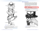
Cabling the Enclosure
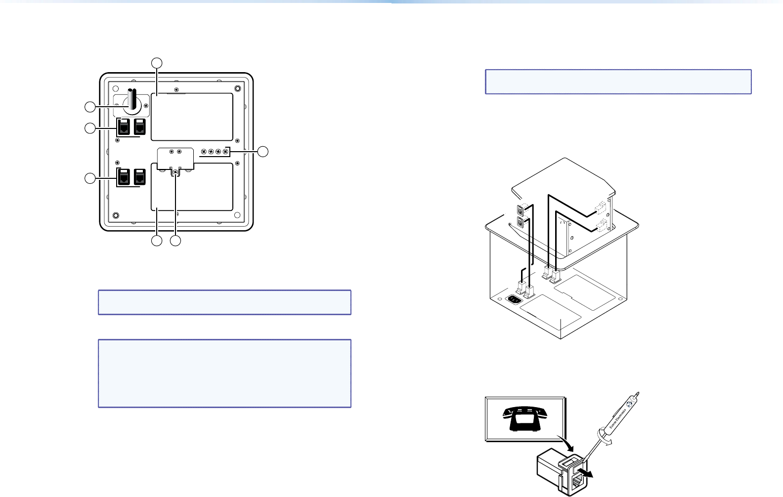
Bottom Panel Features
3
3 5
4
1
2
1
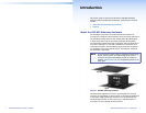
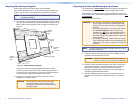
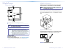
Figure 8. HSA 822 Enclosure Underside Connectors
a
RJ-45 connectors — See “Cabling the RJ-45 connectors”, on the
next page.
NOTE: All RJ-45 connectors are teminated in accordance with
the TIA/EIA T 568 A standard.
b
AC power connector — Connect this cord to the power source.
NOTES: • ForUSdomesticversions,thispowercordis
permanently connected to the HSA. Connect the
power cord to a 125 VAC, 60 Hz, 10 A power source.
• For international versions, this power cord is a
removable IEC power cord. Connect the cord to a
220-250 V, 50-60 Hz, 10 A power source.
c
Cable access holes
d
Spare AAP panel screws
e
Top panel height adjustment screw — See “Adjusting the Height
of the Top Surface” in the “Maintenance and Modifications”
section.
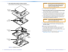
Cabling the RJ-45 connectors
Plug one end of a CAT 6 twisted pair (TP) cable into each of these
RJ-45 female connectors. Connect the other end to an appropriate
telecommunications or data network or to an Extron TP product.
NOTE: All RJ-45 connectors are terminated in accordance with
the TIA/EIA T 568 A standard.
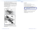
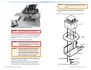
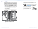
When cabling the AAP panels and the bottom panel, the bottom
RJ-45 connectors match up with the AAP panel RJ-45 connectors as
shown in figure 9. For example, match the AAP panel RJ-45 connector
A1 with the underside RJ-45 connector A1, match A2 with A2, and so
forth.
A1
A2
B1
B2
A1
A2
B1
B2
Figure 9. HSA 822 RJ-45 Connectors
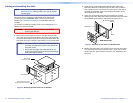
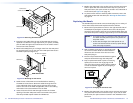
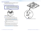
If necessary, replace the connector icon on the AAP panel by prying
the old icon off of the connector plug-in with a tweeker or small
screwdriver (see figure 10) and snapping a new icon in place.
Icon Labels
Figure 10. Changing the Connector Icon
12 HSA 822 Hideaway Enclosure • Installation 13HSA 822 Hideaway Enclosure • Installation