


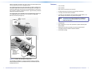
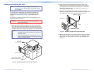
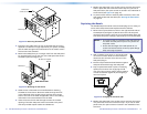
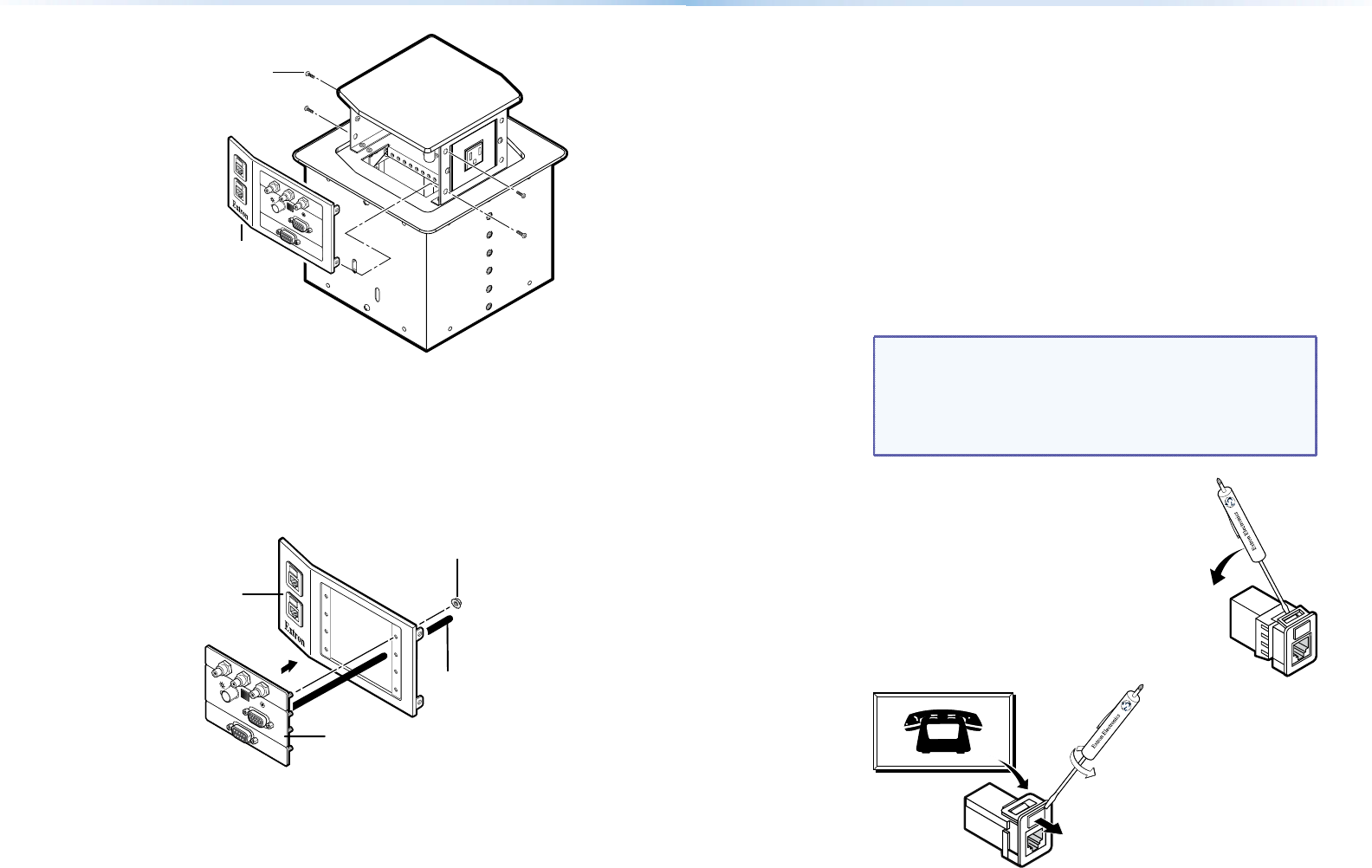
Remove panel.
Remove two
screws ea. side.
HSA 822
C
O
M
P
U
T
E
R
IN
P
U
T
S
E
L
E
C
T
AUDIO
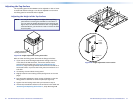
Figure 12. Removing the AAP Panel
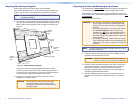
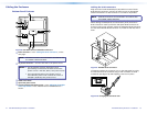
3. Disconnect any cables from the rear of the AAPs that are being
replaced. If a cable is no longer required in your system, carefully
pull the cable through and out the bottom of the surface mount
enclosure and the clamshell.
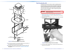
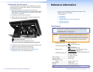
4. Remove the AAP(s) that you no longer want from the AAP panel
by unscrewing the nuts on the rear of the AAP panel that secure
the AAPs in place (see figure 13).
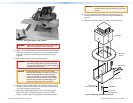
#4-40 Nut w/ Captive
Washer
Cable
AAP Panel
HSA 822
RGB 580xi SI AAP
COMPUTER
INPUT
SELECT
AUDIO
Figure 13. Mounting an AAP Device
5. Cable the rear of the AAPs to be installed before attaching
the AAPs to the enclosure. Route the cables through the hole
in the underside of the surface mount enclosure and connect
them to the rear of the AAPs. If applicable, refer to the cabling
information in the documentation for the AAP.
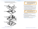
6. Insert the screws of each AAP through the holes in the AAP
opening of the HSA AAP panel. Secure each AAP to the panel
with the provided captive washers and #4-40 nuts.
7. Replace the AAP panel in the surface mount enclosure and secure
them in place with the screws removed in step 2. If you lose an
AAP panel screw, four spare screws are stored in the underside of
the enclosure (see figure 8 on page 12).
8. To prevent wear and tear caused by cable movement, secure the
AAP cables underneath the table (see “Routing the AAP Cables”
on page 14.
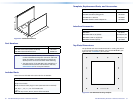
Replacing the Bezels
The HSA 822 ships with RJ-45 connector bezel plug-ins in a variety of
colors and a black, blank bezel. Replace a bezel as follows:
1. Remove the top and bottom screws on the right and left sides of
the AAP panel (see figure 12). Retain the screws. Lift the panel
away from the enclosure as far as the connected cables allow and
then allow the panel to dangle, supported by its connected cables.
NOTES: • ThecenterscrewsoneachsideoftheAAPpaneldo
not fasten the AAP panel in place. They secure the
AC power outlet.
• Ensure that the edges of the AAP panels do not
scratch the finished surface of the top panel flange
when removing the panels.
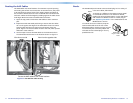
2. With a Tweeker, push down on and gently twist
on the front of each RJ-45 connector detent to
disconnect the connector from the rear of the
AAP panel plug-in.
3. Pinch the top and bottom bezel detents together
and push the bezel through the AAP panel.
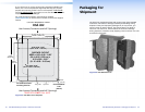
4. Snap a replacement bezel in place. If necessary,
replace the connector icon by prying the old
icon off of the connector plug-in with a Tweeker
or small screwdriver (figure 14) and snapping a
new icon in place.
Icon Labels
Figure 14. Changing the Connector Icon
5. Replace the AAP panel in the surface mount enclosure and secure
it in place with the screws removed in step 1. If you lose an AAP
panel screw, four spare screws are stored in the underside of the
enclosure.
18 HSA 822 Hideaway Enclosure • Maintenance and Modications 19HSA 822 Hideaway Enclosure • Maintenance and Modications