


Installation, cont’d
MAV Series Switchers • Installation2-6
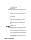
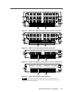
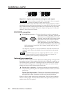
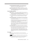
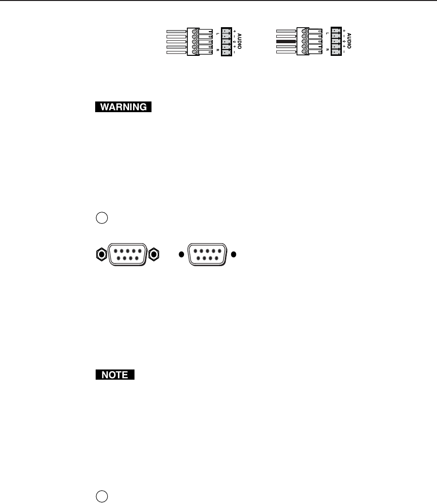
Unbalanced Output
Tip
See warning
Sleeve
Tip
See warning
Balanced Output
Tip
Ring
Sleeve (s)
Tip
Ring
Figure 2-8 — Captive screw connector wiring for audio output
Connect the sleeve to ground (Gnd). Connecting the sleeve to a negative
(-) terminal will damage the audio output circuits.
By default, the audio output follows the video switch. Audio breakaway, which is
commanded via the front panel (see chapter 3) or under RS-232/422 control, via the
SIS or Windows-based control program, allows you to select from any one of the
audio input sources. See chapter 3, Operation, chapter 4, Programmer’s Guide, and
chapter 5, Matrix Software for details.
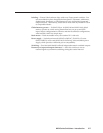
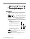
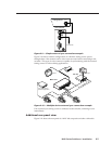
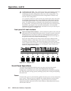
RS-232/422 connection
6
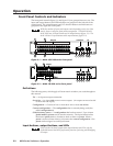
RS-232/RS-422 connector — Connect a host device, such as a computer or
touch panel control, to the MAV via this 9-pin
D connector for serial RS-232/RS-422 control.
If desired, attach an MCP 1000 remote control
panel master unit to the switcher’s RS-232/
RS-422 connector. You can also attach an
MKP 1000 remote keypad or MCP 1000 slave
unit to the MCP 1000 master unit. Refer to the
MCP 1000 Remote Control Panel User’s Manual and the MKP 1000 User’s
Manual for details.
See chapter 4, Programmer’s Guide, for definitions of the SIS commands and
chapter 5, Matrix Software for details on how to install and use the control
software.
The MAV switchers are factory configured for RS-232 control. To use the
switcher under RS-422 control, an internal cable must be moved. See
appendix B for the procedure for shifting the cable.
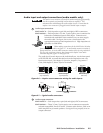
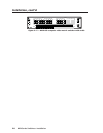
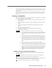
External sync connection
When the switcher switches between inputs, the resulting change in image should
be seamless, or clean. Video models of the MAV 1616/168 Series switcher can use
an external signal to synchronize switching during the vertical interval. Without
the external sync locking feature, switching between inputs can result in a brief
rolling (sync loss) or a brief change in the picture size.
7
External Sync In connector — Connect an external sync signal to this BNC
connection for genlocking the video signal in broadcast or other sync-critical
applications.
External Sync Out connector — Connect any downstream equipment that
requires genlocking to this BNC connector to route the external sync signal
throughout the system in broadcast or other sync-critical applications.
Figure 2-9 shows a basic external sync configuration. The Ext Sync In connector
receives a timing signal. The Out connector allows the signal to be passed on to
another video device, if required.
Female
51
96
Male
15
69