


MLC 104 Plus Series • Hardware Setup
Hardware Setup, cont’d
2-8
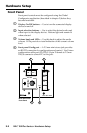
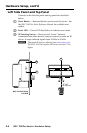
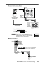
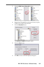
Device Connections
The following illustrations show examples of A/V and control
device connections for all models.
Display connection
Projector
Panel
MLC 104 Plus Series
Right Side Panel
DISPLAY
RS-232/IR
GROUND
IR OUT
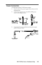
Tx
Rx
Ground ( )
Receive (Rx)
Tr ansmit (Tx)
Ground ( )
Receive (Rx)
Tr ansmit (Tx)
Bidirectional
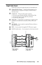
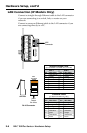
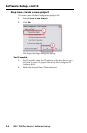
Infrared (IR) connection
MLC 104 Plus Series
Right Side Panel
DISPLAY
RS-232/IR
GROUND
IR OUT
Tx
Rx
G = Ground
IR Emitter 1
White Striped Wire
100'
(30.5 m)
S = Signal (IR)
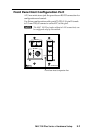
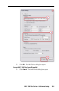
Digital I/O connection
MLC 104 Plus Series
Right Side
IPA T RLY4
Front Panel
1
2
3
GROUND
+12V OUT
CM
GROUND
IR OUT
GROUND
SCP
GROUND
Tx
Rx
DISPLAY
RS-232/IR
A B C D E
COMM LINK
LAN
PRESS TAB WITH
TWEEKER TO REMOVE
A B
MLS
RS-232
POWER
12V
DIGITAL
I/O
IR IN
Tx
GROUND
Rx
+12V IN
IPA T RLY4
1 2 3 4 C
INPUTS
Relay 1
Relay 2
Relay 3
+12 VDC