


MLC 104 Plus Series • Hardware Setup
2-9
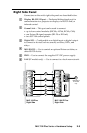
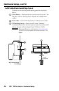
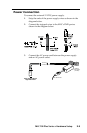
Comm Link connection
MLC 104 Plus Series
Right Side Panel
COMM LINK
A B C D E
+V OUT
GROUND
CM
IR IN
SCP
E
C
B
A
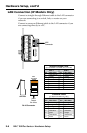
SCP communication (IR)
Ground ( )
IRCM, ACM, RCM, CM
+12 VDC
C
B
A
Maximum =
2 SCPs
Per System
Maximum =
4 Control
Modules
(4 module
addresses)
Ground ( )
+12 VDC
Ground ( ) & Drain Wire
E
C
B
A
SCP Communication
Control Module Communication
+12 VDC
= White
= Black & Drain Wire
= Violet
= Red
IRCM, ACM, RCM, CM
DVD & VCR CONTROL
PLAY NEXT/FWD PAUSESTOP
TUNER
Tx
PREV/REW
ENTER
TITLE MENU
TV/VCR
DVDVCR
SCP 104
IRCM-DV+
CONFIG
DISPLAY
VOLUME
SCP 104
ON
PC
VCR
DVD
OFF
1
2
3
4
200' (61 m) max.
to Last Device
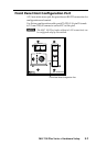
Extron CTLP Cable Color Code:
N
When an SCP 104 is connected to one of
these controllers, the SCP's DIP switch #4
must be in the ON (up) position.
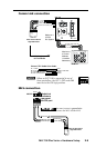
MLS connection
MLC/IR
ABC
MediaLink
Switcher's
rear panel
MLC/IR port
You must connect a ground wire
between the MLC and the MLS.
RS-232
MLS
AB
Rx
Tx
GROUND
Ground ( )
Transmit (Tx)
B
Receive (Rx)
A
Transmit (Tx)
Receive (Rx)
B
A
MLC 104 Plus Series
Right Side Panel
1
ON
234