


MediaLink VersaTools Switchers • Serial Communication
MediaLink VersaTools Switchers • Serial Communication
Serial Communication
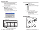
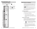
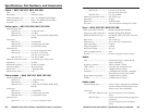
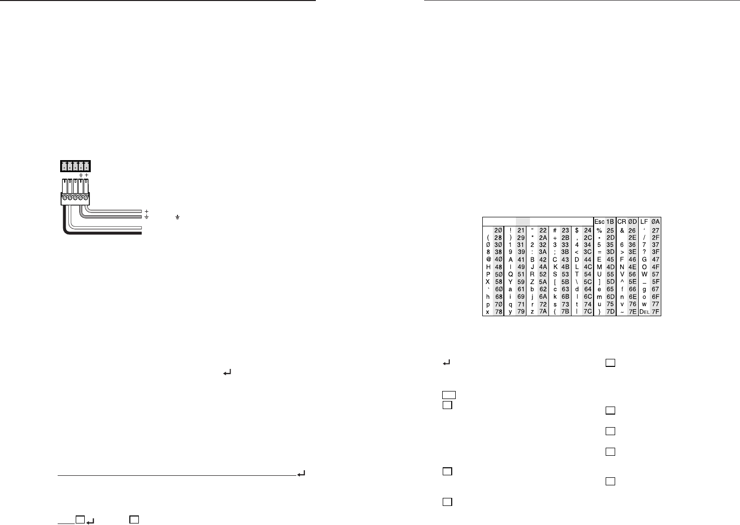
ASCII to HEX Conversion Table
•
4-3
MLC
/RS-232
POWER
AB
MLS100Series
Switcher
MLC/RS-232
Power Port
Ground ( )
+12VDC
Transmit (Tx)
B
Receive (Rx)
A
4-2
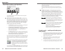
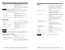
Error responses
When the MLS receives a valid SIS command, it executes the
command and sends a response to the host device. If the MLS is
unable to execute the command because the command is invalid
or it contains invalid parameters, it returns an error response to the
host. Error response codes and their descriptions are as follows:
E01 – Invalid input channel number (the number is too large)
E10 – Invalid command
E13 – Invalid value (the number is out of range/too large)
E14 – Invalid for this configuration.
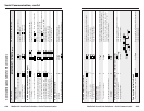
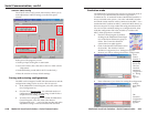
Using the command/response tables
The command/response tables on the next page list valid
command ASCII codes, the MLS’s responses to the host, and a
description of the command’s function or the results of
executing the command. Unless otherwise indicated (as for the
gain commands), upper and lower case characters may be used
interchangeably in the command field.
The ASCII to
HEX conversion
table at left is
for use with the
command/
response tables.
X4
= Input to be adjusted (1 – 4)
1 = input 1
2 = input 2
3 = input 3
4 = input 4
X5
= Audio gain/attenuation value
(-18 through +24)
X6
= Volume adjustment range
(0% – 100%)
X7
= On/off status
0 = off/disable
1 = on/enable
X8
= Switcher firmware version
(listed to two decimal places
e.g.: x.xx)
ASCII to Hex conversion table
Symbol definitions
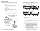
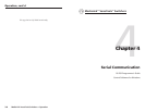
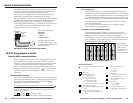
The MediaLink switcher can be remotely set up and controlled
via a host computer or other device (such as a control system)
attached to the rear panel MLC/RS-232 Power port.
Alternatively, the switcher can be controlled by an optional
MediaLink Controller (MLC) (connected to the MLS’s
MLC/RS-232 Power port) or by an RS-232 device acting through
the MLC. The control device (host) can use either the Extron
Simple Instruction Set
™
(SIS
™
) commands or the graphical
control program for Windows
®
. For details on use and setup of
a system that includes a MediaLink Controller, see the
MediaLink Controllers User’s Manual.
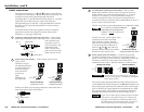
The switcher protocol is
9600 baud
1 stop bit
no parity
no flow control.
The MLC/RS-232 Power
3.5 mm, 5-pole captive screw
connector’s pin assignments
are shown at left.
MLC/RS-232 Power port pin assignments
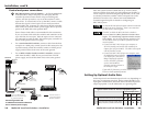
RS-232 Programmer’s Guide
Host-to-MLS communications
SIS commands consist of one or more characters per field. No
special characters are required to begin or end a command
sequence. When the MLS determines that a command is valid,
it executes the command and sends a response to the host
device. All responses from the switcher to the host end with a
carriage return and a line feed (CR/LF = ), which signals the
end of the response character string. A string is one or more
characters.
MLS-initiated messages
When a local event such as a front panel selection or adjustment
takes place, the MLS responds by sending a message to the host.
No response is required from the host. The MLS-initiated
messages are listed here (underlined).
(c)Copyright 2002, Extron Electronics MLS 100 Series, V0.08
The MLS sends the copyright message when it first powers on.
Vx.xx is the firmware version number. The MLS 102 VGA is
used in this example.
Chn
X1
(where
X1
is the input number)
The MLS sends this response when an input is switched.
= CR/LF (carriage return/line feed) (hex
0D 0A)
• = Space
Esc
= Escape key
X1
= Specific input number
(0 – 4 maximum)
0 = no connection
1 = input 1 & Aux/Mix
2 = input 2 & Aux/Mix
3 = input 3 & Aux/Mix
4 = input 4 (audio only) & Aux/Mix
X2
= Audio gain (per input)
0 to 24; 0dB through +24dB in 1dB
steps
X3
= Audio attenuation (per input)
0 to 18; 0dB through -18dB in 1dB
steps)