


MediaLink VersaTools Switchers • Installation
MediaLink VersaTools Switchers • Installation
Installation, cont’d
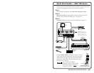
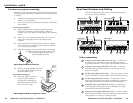
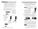
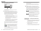
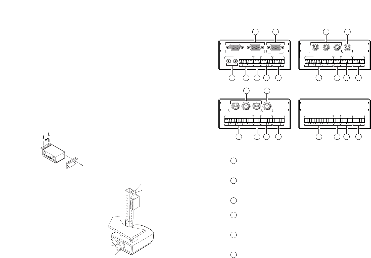
Rear Panel Features and Cabling
Turn off and disconnect power from all the equipment before
you connect cables to the MLS.
3
1
2
OUTPUT
INPUTS
MLS 103 V
LR
A
B
LR
LR
LR
1
2
3
LR
4
AUX/MIX
MONO
AUDIO INPUTS
OUT
MLC/RS-232
POWER
12V .5A MAX
MLS 103 V
3
1
2
OUTPUT
INPUTS
MLS 103 SV
LR
A
B
LR
LR
LR
1
2
3
LR
4
AUX/MIX
MONO
AUDIO INPUTS
OUT
MLC/RS-232
POWER
12V .5A MAX
MLS 103 SV
MLS 100 A
LR
A
B
LR
LR
LR
1
2
3
LR
4
AUX/MIX
MONO
AUDIO INPUTS
OUT
MLC/RS-232
POWER
12V .5A MAX
MLS 100 A
1
2
OUTPUT
INPUTS
MLS 102 VGA
LR
A
B
LR
1
2
3
LR
4
AUX/MIX
MONO
AUDIO INPUTS
OUT
MLC/RS-232
POWER
12V .5A MAX
MLS 102 VGA
11109
11
8
108 9
11108
8
9
8
11109
87
1 2
5 6
3 4
Video connections
1
Computer video inputs (MLS 102 VGA only) — Cable one or
two VGA-UXGA computers to these individually buffered
15-pin HD connectors. These inputs provide ID bit termination.
2
Computer video output (MLS 102 VGA only) — Connect a
cable from this 15-pin HD connector to the input port of the
projector or display.
3
S-video inputs (MLS 103 SV only) — Cable up to three S-video
sources to the MLS via these female 4-pin mini DIN connectors.
4
S-video output (MLS 103 SV only) — Connect the S-video
input port of the projector or display to the MLS by plugging S-
video cables into these female 4-pin mini DIN connectors.
5
Composite video inputs (MLS 103 V only) — Connect up to
three composite video input sources to the MLS 103 V using
coaxial cables and these female BNCs.
6
Composite video output (MLS 103 V only) — Attach a coaxial
cable to this female BNC, and connect the other end of the cable
to the projector’s or display’s video input port.
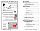
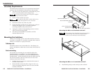
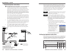
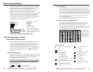
Furniture or projector mounting
Furniture mount or projector mount the MLS using the optional
mounting kit (part #70-212-01, furniture; or 70-217-01, projector)
as follows:
1. Attach the mounting brackets to the MLS with the
machine screws provided.
2. If feet were previously installed on the bottom of the MLS,
remove them.
For furniture mounting
3a. Hold the MLS with the attached brackets against the
underside of the table or other furniture. Mark the
location of the screw holes of the bracket on the mounting
surface.
4a. Drill 3/32” (2 mm) diameter pilot holes, 1/4” (6.3 mm)
deep in the mounting surface at the marked screw
locations.
5a. Insert #8 wood screws into the four pilot holes. Tighten
each screw into the mounting surface until just less than
1/4” of the screw protrudes.
6a. Align the mounting screws with the slots in the brackets
and place the MLS against the surface, with
the screws through the bracket slots.
See the illustration at left.
Mounting the MLS to furniture
7a. Slide the switcher slightly forward or
back, then tighten all four screws to
secure the MLS in place.
For projector mounting
3b. Secure the MLS to a projector
mount or other surface by
inserting the mounting bolt
through the bracket’s slotted
hole, as shown at right.
2-5
MLS 100 Series
M
ediaLink
Sw
itcher
A
U
X
/M
IX
L
E
V
E
L
I
N
P
U
T
S
E
L
E
C
T
1
2
3
4
Ceiling
Digital Projector
Projector
Mounting
Bracket
1
2
O
U
T
P
UT
I
N
PU
T
S
M
L
S
1
0
2
V
G
A
L
R
A
B
L
R
1
2
3
L
R
4
A
UX
/
MIX
MO
N
O
A
U
D
IO
IN
P
UTS
O
UT
C
O
N
T
R
O
L
/
P
O
W
ER
1
2
V
.5
A
M
A
X
Mounting
Bolt
2-4
Mounting the MLS to a projector mount