


MediaLink VersaTools Switchers • Serial Communication
MediaLink VersaTools Switchers • Serial Communication
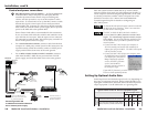
Serial Communication, cont’d
Control Software for Windows
®
The included Extron MediaLink Control Program for Windows
offers another way to control the switcher via RS-232 connection
in addition to the Simple Instruction Set commands. The
control program’s graphical interface includes input selection
functions and some additional features that are only available
through the software.
To set up the MLS 100 Series switcher you must use
MediaLink Control Software version 2.0 or higher.
The control software is compatible with Windows 95/98,
Windows NT, and Windows 2000. Extron’s MediaLink Control
Program is included with the MLS, and updates can be
downloaded from the Extron Web site
(http://www.extron.com).
Installing the software
The control program is contained on a set of 3.5-inch diskettes; it
requires approximately 2 MB (megabytes) of hard disk space.
To install the software on the hard drive:
1. Run SETUP.EXE from the floppy disk.
2. Follow the instructions that appear on the screen.
By default the installation creates a C:\MediaLnk
directory, and it places two icons (MediaLnk Control Pgm
and MediaLnk Help) into a group or folder named “Extron
Electronics”.
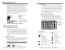
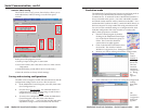
Using the control program
The MediaLink Help Program provides information on settings
and on how to use the control program itself. Some features are
only available via this control program. These features are
described in the sections of this chapter that correspond to the
parts of the control program where the features are found.
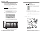
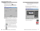
1. To run the control program, double-click on the MediaLnk
Control Pgm icon in the Extron Electronics
group or folder. The Comm Port Selection
menu appears on the screen.
2. Click on the comm port that is connected to the MLS’s
RS-232 port. The Extron MediaLink Control Program
windows appear. The port and firmware information are
displayed at the bottom of the screen. There are two views
available: the User Mode screen, and the Switcher (MLS)
Configuration screen.
4-7
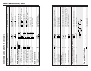
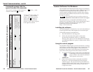
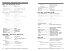
Command/response table for
special function SIS commands
The syntax for setting a special function is __ *
X?
# where __ is the
function number and
X?
is the value.
Command/response table for special function SIS commands
Command ASCII Command Response
X?
values
(host to switcher) (switcher to host) and additional descriptions
Delay times
Set the RGB delay. 3 *
X?
# RGBDly*
X?
0 = 0.0 seconds (default), 1 = 0.5
seconds, 2 = 1.0 seconds,
... in ½ second steps up to
10 = 5.0 seconds
Example: 3*7# RGBDly*07
Example: 3.5 second RGB delay.
To view a function’s setting, use
__#, where __ is the function
number. In the table at left the
values of the
X?
variable are
different for each command/
function. These values are given
in the rightmost column.
4-6