


MediaLink VersaTools Switchers • Installation
MediaLink VersaTools Switchers • Installation
Installation, cont’d
9
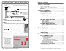
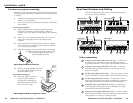
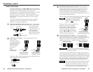
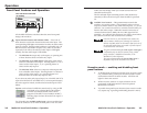
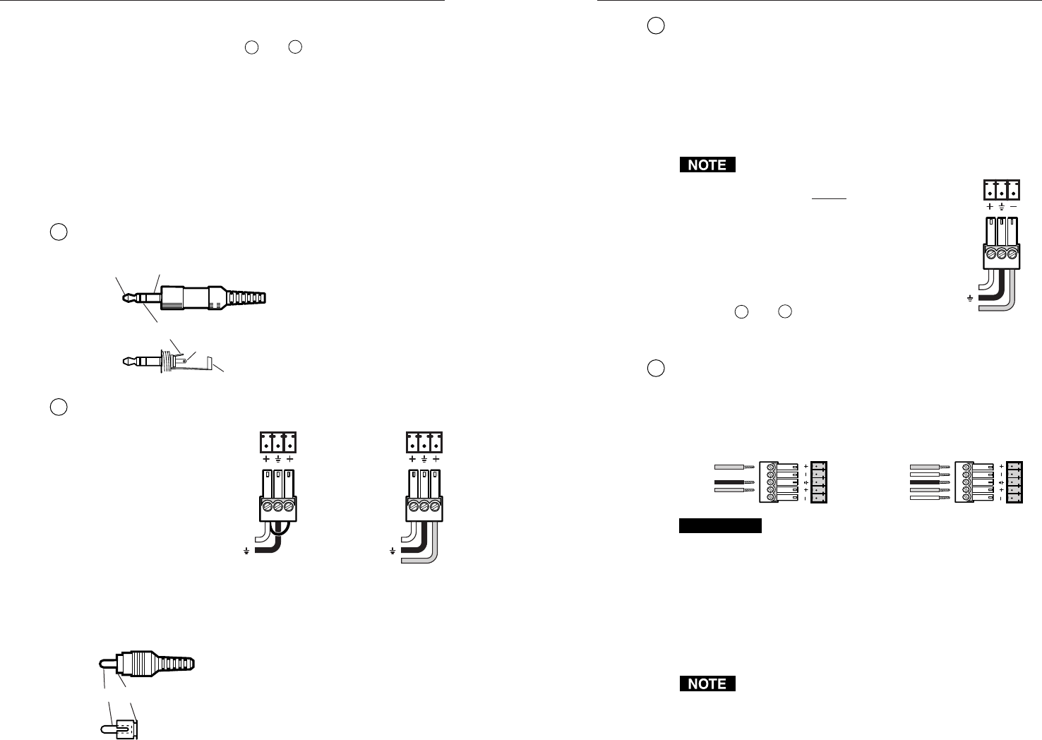
Aux/Mix Mono audio input (all models) —The Aux/Mix
Mono audio channel is always active: its signal is output no
matter which, if any, other audio input (input 1, 2, 3, or 4) is
selected. For example, you could connect the output of a
wireless microphone receiver to this port so the presenter’s
comments can always be heard and are independent of the A/V
source used for the presentation.
The mix output level can be adjusted between -43dB and +24dB.
The Aux/Mix level must be adjusted
physically via the front panel
control. It cannot be adjusted via
software.
Connect a 3.5 mm, 3-pole captive screw
connector to one end of an audio
cable as shown at right. Wire the
other end to two tip-ring connectors
or one tip-ring-sleeve connector as
shown in
7
and
8
, and connect it
between the MLS 100 Series switcher
and the auxiliary audio source.
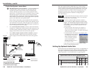
10
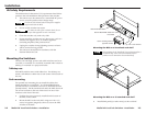
Audio output (Out) (all models) — Connect self-powered
speakers or another stereo audio device to the MLS via this
5-pole 3.5 mm captive screw connector. Depending on how the
connector is wired, the audio output can be balanced or
unbalanced stereo audio. Wire the connector as shown below.
Unbalanced Output
Tip
See Caution
Sleeve (s)
Tip
See Caution
Balanced Output
Tip
Ring
Sleeve (s)
Tip
Ring
LR
OUT
OUT
LR
CAUTION
Connect the sleeve to ground (Gnd). Connecting
the sleeve to a negative (-) terminal will damage the
audio output circuits.
Later, after all the equipment has been cabled and powered on,
use the MediaLink Control Program or an RS-232 controller to set
the per-input gain/attenuation to match the correct audio output
level for the kind of output (balanced or unbalanced) you need.
See pages 2-9 and 4-10 for details on determining and setting
the gain/attenuation to produce the desired output levels.
If you wire an audio output for balanced output, the MLS
will output a unity signal (input level = output level).
Wiring an audio output for unbalanced output causes
the audio signal to be attenuated by 6dB. See pages 2-9
and 2-10 for instructions on adjusting audio gain.
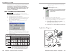
Audio connections
The stereo audio inputs 1–3 (
7
and
8
on page 2-5 and below)
correspond to video inputs 1, 2, and 3. All four audio inputs can
be selected via the front panel buttons, RS-232 control
(including MLC), or the MediaLink Control Software. An audio
signal from one of these inputs is output only when the
corresponding input is selected. Using the MediaLink Control
Software you can separately adjust the level of each of these
audio inputs.
Via RS-232 control audio input signals can also be switched
separately from the video signals (a feature called “audio
breakaway”.) See pages 4-4 and 4-8.
7
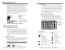
Computer audio inputs (MLS 102 VGA only) — These inputs
each accept unbalanced stereo audio input via a 3.5 mm stereo
mini receptacle (tip-
ring-sleeve type). If
you do not have a pre-
terminated audio
cable, wire the mini
jack on each end of the
cable as shown at left.
8
Audio Inputs (all models) — Each of these 3-pole 3.5 mm
captive screw
connectors accepts
one unbalanced stereo
or mono audio input.
Wire each captive
screw connector
as shown at
right,
depending on
the input type.
Connect two RCA-style (tip-ring) connectors to the other end of
each audio input cable as shown here:
Tip (+) Sleeve (Gnd)
2-72-6
Aux/Mix Input Wiring
(balanced/unbalanced, mono)
AUX
/
MIX
MONO
Tip (+)
Ring (–)
Gnd (Sleeve, )
Tip (+) Sleeve (Gnd)
Tip (L, +)
Ring (R, -)
Sleeve (Gnd)
LR
Audio Input Wiring
(unbalanced, stereo
)
LR
Audio Input Wiring
(unbalanced, mono)
Left (+)
Right (+)
Gnd (Sleeve, )
Left (+)
Gnd (Sleeve, )