


VersaTools
®
MTP 15HD A Series • InstallationVersaTools
®
MTP 15HD A Series • Installation
VersaTools
®
MTP 15HD A Series, cont’d
VersaTools
®
MTP 15HD A Series • Connections and Settings VersaTools
®
MTP 15HD A Series • Connections and Settings
10
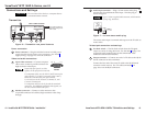
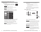
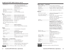
DIP switches
Horizontal Sync switch (1) — Set this switch up
for positive horizontal sync (or positive composite
sync if the Composite Sync switch is on) or down
for negative sync.
Most devices use negative sync.
Vertical Sync switch (2) — Set this switch up for positive
vertical sync or down for negative sync.
Most devices use negative sync.
Composite Sync switch (3) — Set this switch up for RGBS or
down to output RGBHV or RGsB video. See the table below.
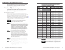
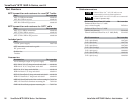
Output signal
format from
the receiver
Input signal
format to the
transmitter
Receiver's DIP
switch settings
C Sync SOG Video
RGBHV
RGBSRGBHV
RGsB
RGBS
RGsB
RGsB
Component
S-video
Composite
RGBS
RGsB
RsGsBsRsGsBs
Component
S-video
Composite
Sync-on-Green (SOG) switch (4) — Set this switch up for RGsB
video (when the input is RGBHV or RGBS) or down to output
RGBHV, RsGsBs, or RGBS video. See the table above.
Video switch (5) — Set this switch up for RsGsBs, RGsB,
component/S-video/composite video or down to output
RGBHV or RGBS video. See the table above.
Set the Composite Sync, SOG, and Video DIP switches
as shown in the table above for the various input and
output video formats.
End Unit switch (6) — Set this switch up if either of the
following is true:
• The receiver being configured is the only receiver
connected to the transmitter.
• The receiver being configured is the last receiver in a
daisy-chained system.
If there are one or more receivers connected to the Buffered
Output RJ-45 connector on the receiver being configured, set
that receiver’s End Unit switch down.
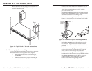
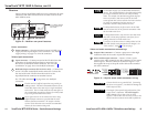
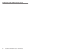
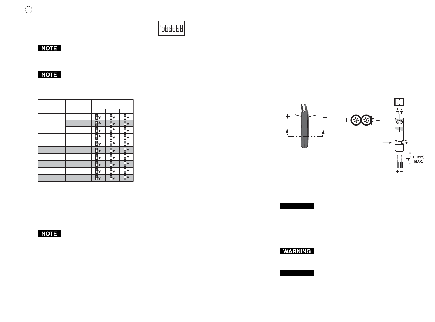
Power supply wiring
Figure 10 shows how to wire the power connector.
Power Supply
Output Cord
Captive Screw
Connector
3
5
SECTION A–A
Ridges
Smooth
AA
Tie Wrap
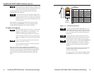
Figure 10 — Power connector wiring
CAUTION
Power supply voltage polarity is critical. Incorrect
voltage polarity can damage the power supply and
the MTP. Identify the power cord negative lead by
the ridges on the side of the cord (figure 10).
To verify the polarity before connection, plug in the power
supply with no load and check the output with a voltmeter.
The two power cord wires must be kept separate
while the power supply is plugged in. Remove
power before wiring.
CAUTION
The length of the exposed (stripped) copper wires is
important. The ideal length is 3/16" (5 mm).
Longer bare wires can short together. Shorter wires
are not as secure in the direct insertion connectors
and could be pulled out.
16 17
ON
1 2 3 4 5 6
H SYNC +
V SYNC +
C SYNC
SOG
VIDEO
END UNIT