


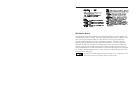
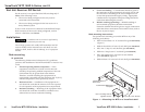
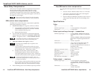

VersaTools
®
MTP 15HD A Series • InstallationVersaTools
®
MTP 15HD A Series • Installation
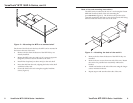
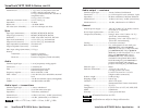
VersaTools
®
MTP 15HD A Series, cont’d
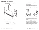
VersaTools
®
MTP 15HD A Series • SpecificationsVersaTools
®
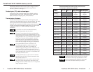
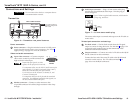
MTP 15HD A Series • Skew Delay Compensation
Skew Delay Compensation
CAT 5/5e/6/7 TP cable can lead to registration errors between
the red, green, and blue video signals. Pair skew can be
measured with test equipment or identified by viewing a
crosshatch test pattern with a critical eye to determine if either
the red, green, or blue video image leads (appears to the left of)
the other two video images.
Unless the TP cable is changed, the skew adjustment
should need to be made only once, during installation.
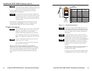
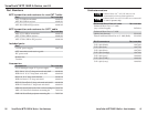
SEQ receiver skew compensation
The SEQ receiver has built-in skew compensation capabilities.
Adjust the equalization as follows:
1. Zero the skew delay for red, green, and blue as follows:
a. Use a Tweeker or other small screwdriver to press
and hold the Select button for 3 seconds. The Red,
Green, and Blue LEDs all go out.
b. Release the Select button.
2. Use UTP cable test equipment or examine the displayed
video image with a critical eye to determine which video
signal — red, green, or blue — is most shifted to the left.
A crosshatch test pattern or a black background with
vertical white lines is ideal for determining skew.
3. Adjust the leftmost video signal as follows:
The SEQ receiver cannot shift the rightmost video
image to the left.
a. Use a Tweeker or other small screwdriver to press
and release the Select button until the LED lights for
the left-shifted color — Red, Green, or Blue.
b. Slowly rotate the Delay control clockwise while
monitoring the display. Observe that the leftmost
color shifts rightward one step at a time. Continue to
rotate the control until that color is properly converged.
A 2-nanosecond adjustment is very fine. Up to 10
nanoseconds of delay may be necessary before you detect
a change in the display.
c. Use a Tweeker or other small screwdriver to press the
Select button one more time to save the most recent
adjustment or allow the 10-second timeout to elapse.
4. If the remaining colors are left shifted, repeat steps 2 and 3.
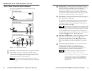
Non-SEQ receiver skew compensation
Try using the following methods to minimize or eliminate pair
skew:
• Switch to Extron’s Enhanced Skew-Free A/V UTP cable.
• Add a skew compensation cable equal to the length of
pair skew to the receiver’s output.
• Install an SEQ 100 15HD Skew Equalizer on the receiver’s
video output and adjust the skew for the leading video
image.
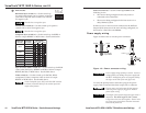
Specifications
Video
Gain ............................................... Unity
Number/signal type ................... 1 set of proprietary analog signals
Connectors .................................... 1 female RJ-45
Video input and loop through — transmitters
Number/signal type ................... 1 analog RGBHV, RGBS, RGsB, RsGsBs,
component video, S-video, or composite
video
1 buffered RGBHV, RGBS, RGsB, RsGsBs
local monitor loop through (includes ID
bits)
Connectors .................................... 2 female 15-pin HD
Nominal level ............................... 1 V p-p for Y of component video and
S-video, and for composite video
0.7 V p-p for RGB and for R-Y and B-Y of
component video
0.3 V p-p for C of S-video
Minimum/maximum levels ...... 0.3 V to 1.45 V p-p
Impedance .................................... 75 ohms
Horizontal frequency .................. 15 kHz to 130 kHz
Vertical frequency ....................... 30 Hz to 150 Hz
Return loss .................................... <-30 dB @ 5 MHz
DC offset (max. allowable) ......... 250 mV
Video output — receivers
Number/signal type ................... 1 set of proprietary analog signals
1 analog RGBHV, RGBS, RGsB, RsGsBs,
component video, S-video, or composite
video
Connectors .................................... 1 female RJ-45
1 female 15-pin HD
2322