


Installation, cont’d
MVX 44 / 48 / 84 / 88 VGA Matrix Switchers • Installation2-2
Installation
Mounting the Switcher
Keep the switcher out of bright light to prevent interference with the IR
signals from the IR 501 remote control.
Tabletop use
For tabletop use, affix one of the supplied self-adhesive rubber feet to each corner
of the bottom of the switcher.
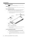
Rack mounting the switcher
All of the MVX Series VGA switcher models are housed in rack-mountable, 1U
high, full rack wide metal enclosures. The appropriate rack mounting kit is
included with each switcher. Rack mount the switcher as follows:
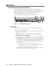
1. If feet were previously installed on the bottom of the switcher, remove them.
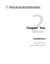
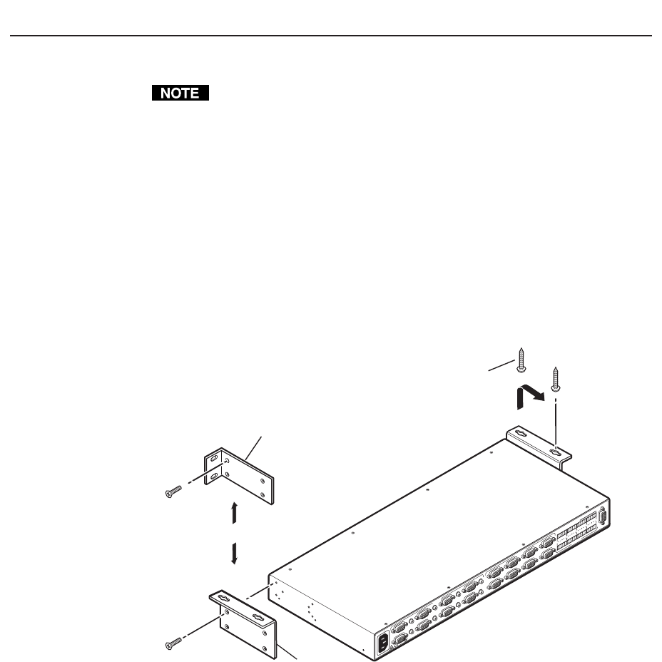
2. Attach the rack mount brackets to the switcher with the eight #8 machine
screws provided (figure 2-1).
1
0
0
-
2
4
0
V
0
.
3
A
5
0
-
6
0
H
z
MVX 88 V
GA A
RS-232
O
UTP
UTS
L
R
7
L
R
8
L
R
5
L
R
6
L
R
3
L
R
4
L
R
1
L
R
2
C
U
S
L
IS
T
E
D
1
T
2
3
I
.
T
.
E
.
1
2
3
4
INPUTS
5
6
7
8
1
2
O
UTPUTS
3
4
5
6
7
8
Rack-mount
Bracket (Included)
Table/
Wall-mount
Bracket (Optional)
Drill pilot holes
3/32” (2 mm) dia.,
1/4” (6 mm) deep.
#8 Screw (4 Plcs)
Each Side
Mounting Screws (2 Plcs)
Each Side
or
Figure 2-1 — Mounting the switcher
3. Insert the switcher into the rack, aligning the holes in the mounting bracket
with those of the rack.
4. Secure the switcher to the rack using the supplied machine screws.
Furniture mounting the switcher
The MVX Series switchers can be mounted under a table or other horizontal
surface with an optional Extron under-desk mounting kit (part #70-222-01).
1. Secure the two table/wall mounting brackets to the switcher with the eight
machine screws provided in the kit (figure 2-1).
2. Hold the switcher with attached brackets against the underside of the desk or
other furniture. Mark the location of holes for screws on the underside of the
desk.