


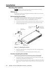
2-5MVX 44 / 48 / 84 / 88 VGA Matrix Switchers • Installation
Remote connection
4
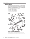
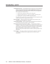
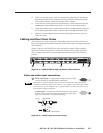
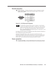
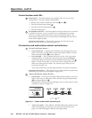
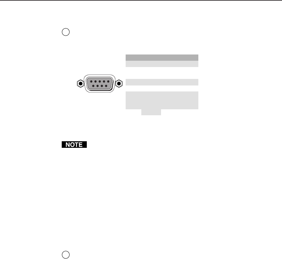
RS-232 connector — Connect a host device, such as a computer or control
system, to the switcher via this 9-pin D connector (figure 2-5) for remote
control of the switcher.
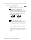
Pin RS-232 Function
1 — Not used
2 TX Transmit data (-)
3 RX Receive data (+)
4 — Not used
5 Gnd Signal ground
6 — Not used
Not used
Not used
7—
8—
—
51
96
Female
Hardwired IR9
Figure 2-5 — RS-232 port pin assignment
The cable used to connect the RS-232 port to a computer or control system
may need to be modified by removing pins or cutting wires. If you encounter
problems while operating under RS-232 control (the switcher may hang up),
pins 1, 4, 6, 7, and 8 may need to be disconnected. Either cut the wire to
pins 1, 4, and 6 through 8 in a hard-shelled connector or remove pins 1, 4, and
6 through 8 from a molded plug.
See chapter 4, Remote Operation, for definitions of the SIS commands and details on
how to install and use the control software.
Using the hardwired IR input on pin 9, you can use a control system with
IR-learning capabilities to operate the switcher just as if you were using an IR 501
remote control. The control system must first “learn” the IR command from an
IR 501, after which it sends the same commands to the MVX via pin 9.
Power connection
5
AC power connector — Plug a standard IEC power cord into this connector
to connect the switcher to a 100 VAC to 240 VAC, 50 or 60 Hz power source.