


3-3MVX 44 / 48 / 84 / 88 VGA Matrix Switchers • Operation
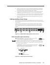
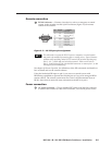
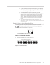
Power/audio/data LED and infrared sensor
1
Infrared remote sensor — This sensor receives infrared (IR) signals from the
optional IR 501 small matrix universal remote control. The IR remote control
must be pointed within 30 degrees of this sensor for best results.
Operation of the IR 501 remote control is described in the IR 501 Small Matrix
IR Remote Control User’s Guide.
Keep the switcher out of bright light to prevent interference with the IR signals
from the IR 501 remote control.
2
Power/data/audio LED —
• When lit, the Power LED indicates that power is applied to the matrix
switcher.
• When blinking off and on, the Power LED indicates that an IR signal
has been received.
• In Audio Setup mode, the Power LED also serves as an audio meter that
is tied to output 1. The LED blinks frequently when the selected input’s
audio level has been adjusted to the –10 dBV internal reference level.
(In Audio Setup mode, the selected input’s audio is automatically tied to
output 1.) See Adjusting input audio gain and attenuation on page 3-18 and
Optimizing the Audio on page 3-26.
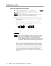
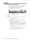
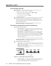
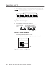
Input and output selection controls and indicators
If the switcher has fewer than eight inputs or outputs, it has fewer input or
output buttons and LEDs.
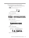
3
Input buttons and LEDs — The input buttons and LEDs select and identify
inputs.
Alternate preset selection function — The input buttons and LEDs also serve
as preset selection buttons and indicators, allowing you to select presets to
either save or recall. A more detailed explanation of the presets functions is
included in Using presets, beginning on page 3-16.
4
Output buttons and LEDs — The output buttons and LEDs select and
identify outputs.
Alternate preset selection function — The output buttons and LEDs also
serve as preset selection buttons and indicators, allowing you to select presets
to either save or recall. A more detailed explanation of the presets functions is
included in Using presets, beginning on page 3-16.
Alternate audio indication function — The Output 1 through Output 3 LEDs
also serve as the input audio level indicators, each indicating a range of 6 dB
when lit:
• Output 1 LED off = 0 dB to 5 dB
• Output 1 LED lit = 6 dB to 11 dB
• Output 1 and 2 LED lit = 12 dB to 17 dB
• Output 1 through Output 3 LEDs lit = 18 dB
See Adjusting input audio gain and attenuation on page 3-18.
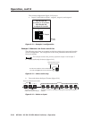
Alternate audio adjustment function — On 8-output switchers, the Output 7
and Output 8 buttons and LEDs also serve as the Down (
) and Up ( )
controls and indicators. See
10
and
11
.