


SW USB Series • Installation
Installation, cont’d
2-6
SW USB Series • Installation
2-7
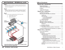
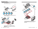
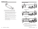
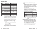
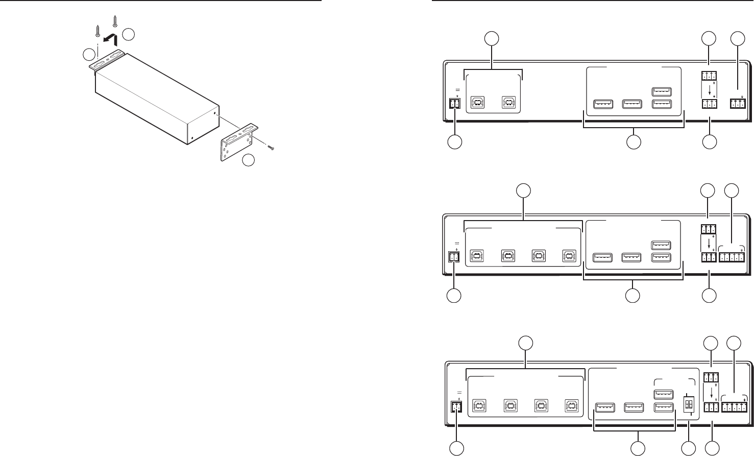
Rear Panel Features
USB SWITCHED INPUT
USB OUTPUT HUB
Tx
Tx Rx
RS-232
CONTACT
1
2
RS-232
PASS THRU
USB 3
USB 1
USB 2
USB 4
1.5A MAX
12V
POWER
+
PC 1
PC 2
1
4
6
3
2
7
SW2 USB rear panel
USB SWITCHED INPUT
USB OUTPUT HUB
Tx
Tx Rx
RS-232
CONTACT
1
2
3
4
RS-232
PASS THRU
USB 3
USB 1
USB 2
USB 4
1.5A MAX
12V
POWER
+
PC 1
PC 2
PC 3
PC 4
1
2
4
6
3
7
SW4 USB rear panel
USB SWITCHED INPUTS
USB OUTPUTS HUB
Tx
Tx Rx
RS-232
RS-232
PASS THRU
USB 3
USB 1
USB 2
USB 4
1.5A MAX
12V
POWER
+
PC 1
PC 2
PC 3
PC 4
MOUSE
1 2
ON
KEYBOARD
ON
OFF
HOST
EMULATION
CONTACT
1
2
3
4
1
4
5
6
3
2
7
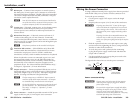
SW4 USB Plus rear panel
a
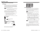
Input connectors — Connect host devices, such as computers,
to these female type B USB connectors, using cable lengths of up
to 15' (4.5 m). Pinouts for these connectors follow the standard
pinout as dened in USB specications.
3
7
9
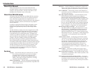
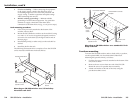
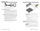
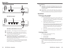
Preparing the SW USB for under-desk mounting
4. Repeat steps 2 and 3 on the other side of the SW USB.
5. Hold the unit with the attached brackets against the
underside of the table or other furniture. On the mounting
surface, mark the location of the brackets’ screw holes.
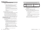
6. Drill 3/32" (2 mm) diameter pilot holes, 1/4" (6.3 mm)
deep, into the mounting surface at the marked screw
locations.
7. Insert #8 wood screws through the bracket holes and into
the four pilot holes. Tighten each screw into the mounting
surface until slightly less than 1/4" of the screw head
protrudes.
8. Align the mounting screws with the slots in the brackets
and place the unit against the surface, with the screws
through the bracket slots.
9. Slide the unit slightly forward or back, then tighten all four
screws to secure it in place.