


SW USB Series • Operation
Operation, cont’d
3-6
SW USB Series • Operation
3-7
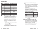
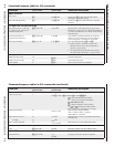
SIS
Command
SW USB Function SW USB Response to Host
!
Performed and passed through
Chn
X!
]
^
Performed, not passed through
USB
X!
]
E
(any)
Performed, not passed through See the SIS command table.
X
Performed, not passed through
Exe
X#
]
N
Performed, not passed through
60-95n-01
Q
Performed, not passed through n.nn
*Q
Performed, not passed through n.nn.nnnn
I
Performed, not passed through
Chn
X!
•InACT
X$
OutACT
X$
]
0V – 100V
Passed through, not performed*
CMD
]
&
Passed through, not performed*
CMD
]
%
Passed through, not performed*
CMD
]
1B, 0B
Passed through, not performed*
CMD
]
1M, 0M
Passed through, not performed*
CMD
]
1Z, 0Z
Passed through, not performed*
CMD
]
$
Passed through, not performed*
CMD
]
* For explanations of commands that are passed through to the
A/V switcher and not performed by the SW USB, refer to your
A/V switcher’s user’s manual.
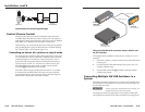
Example: When a control system issues an SIS input selection
command of 1! (Select input 1), 2! (Select input 2), 3! (Select
input 3), or 4! (Select input 4), the SW USB switches to the
corresponding input. In addition, the SW USB passes the SIS
input selection command through the RS-232 Pass Thru port,
causing the same input to be selected on the A/V switcher.
The following SIS commands can not be passed through to the
A/V switcher:
• Information requests: View part number (N) and Request
information (I)
• Change loop mode:
E
nLOOP
• Upload firmware:
E
Upload
See the SIS Command/Response table in chapter 4, “SIS
Conguration and Control,” for explanations of SIS commands
that are performed by the SW USB.
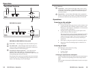
Sending commands to an A/V switcher using contact
closure
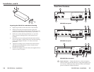
In Loop 0 mode, you can select an input on the SW USB by
shorting the equivalent pin on the Contact port to ground (either
by pressing a button on a connected contact closure device or by
connecting a jumper between pin 1, 2, 3, or 4 and
_
[ground]).
Shorting the pin to ground issues an input selection command to
the SW USB, which passes the SIS command through its RS-232
Pass Thru port to the A/V switcher. The switcher then switches
to the equivalent input.
For example, if you wanted to select input 1 on the
A/V switcher, you would short pin 1 to ground on the
SW USB Contact port. The SW USB switches to input 1 and,
simultaneously, the RS-232 Pass Thru port passes the SIS
command 1! to the A/V switcher, which also switches to input 1.
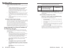
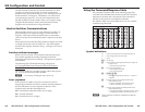
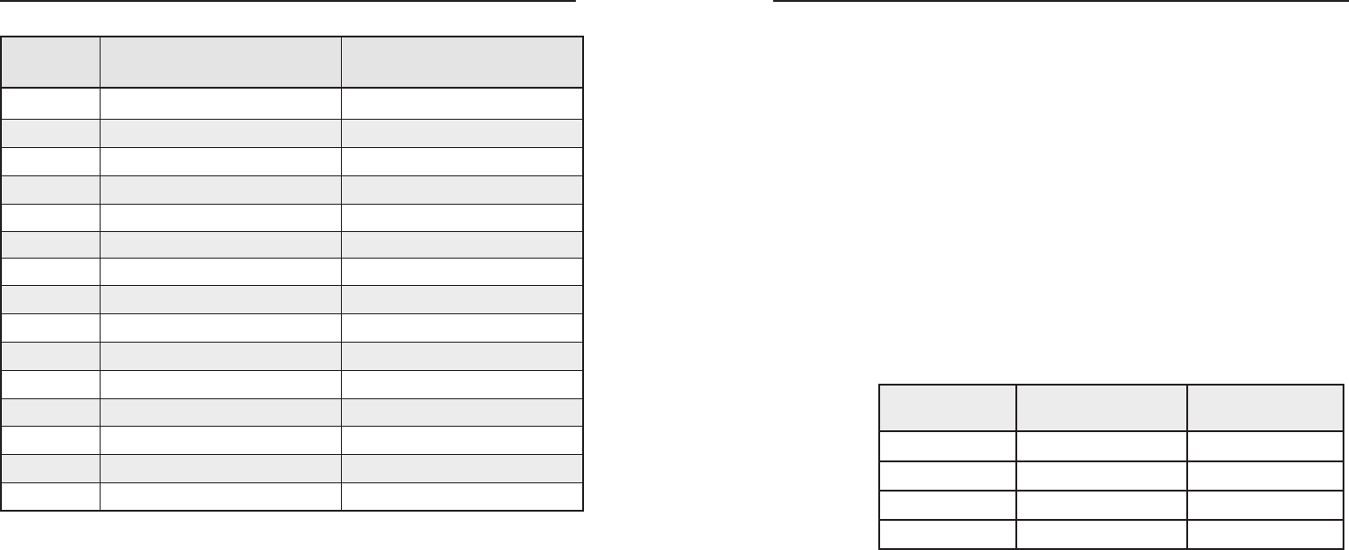
The following table shows the SIS commands that are issued
when inputs are selected by contact closure:
Contact closure
selection
SIS command sent
via RS-232 Pass Thru
Function on the
A/V Sitcher
Pin 1 to _
1! Select input 1
Pin 2 to _
2! Select input 2
Pin 3 to _
3! Select input 3
Pin 4 to _
4! Select input 4
N
When the SW USB is operating in Loop 0 mode,
pressing one of its front panel input buttons or issuing
the SIS command
X!
! also selects the same input on the
A/V switcher.
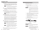
Enabling front panel lockout (executive mode)
Executive mode disables all front panel controls, locking out
the user from those functions. Putting the switcher in this
mode enhances security by protecting against inappropriate or
accidental changes to settings. When the SW USB is in executive
mode, RS-232 and contact closure remain available.
To lock the front panel, press and hold Input buttons 1 and
2 simultaneously for 5 seconds, then release them. The red
Exec Mode LED on the front panel lights, indicating that
executive mode is enabled.