


Installation and Operation, cont’d
SW8/12 VGA Ars • Installation and Operation
2-10
VSW I AAP connection
The VSW I AAP (part #70-529-11, -21, -51) is an optional Architectural Adapter Plate
that provides remote input connection and selection for some Extron switchers.
TheVSWIAAPcanbeconnectedtotheSW8/12VGAArsinputportsforinput
selection control.
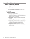
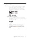
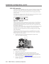
TheVSWIAAPisequippedwitha“ShowMe”buttonforinputselection,afemale
15-pinHDVGAconnector,anda3.5mmstereoaudiojack.
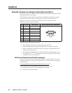
VSW I AAP
COMPUTER
AUDIO
SHOW ME
Figure 2-13 — VSW I AAP
Whenthe“ShowMe”buttonispressed,pin5ontheswitcher’s15-pinHDinput
is momentarily shorted to ground. This overrides the switcher’s current input
selection, and directs video and audio from the VSW I AAP’s connected device to
the switcher’s output ports.
FortheVSWIAAPtooperatewithaswitcher,theVSWIAAPPCBjumpermustbe
set properly, and the switcher must be configured via its RS-232 control port.
The VSW I AAP can be mounted into any Extron mounting frame with a single
space AAP opening.
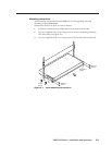
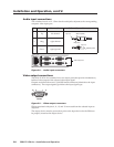
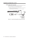
TheillustrationonthefollowingpageshowsatypicalSW8VGAArsswitcher
application with four VSW I AAP units connected to the switcher’s input ports.
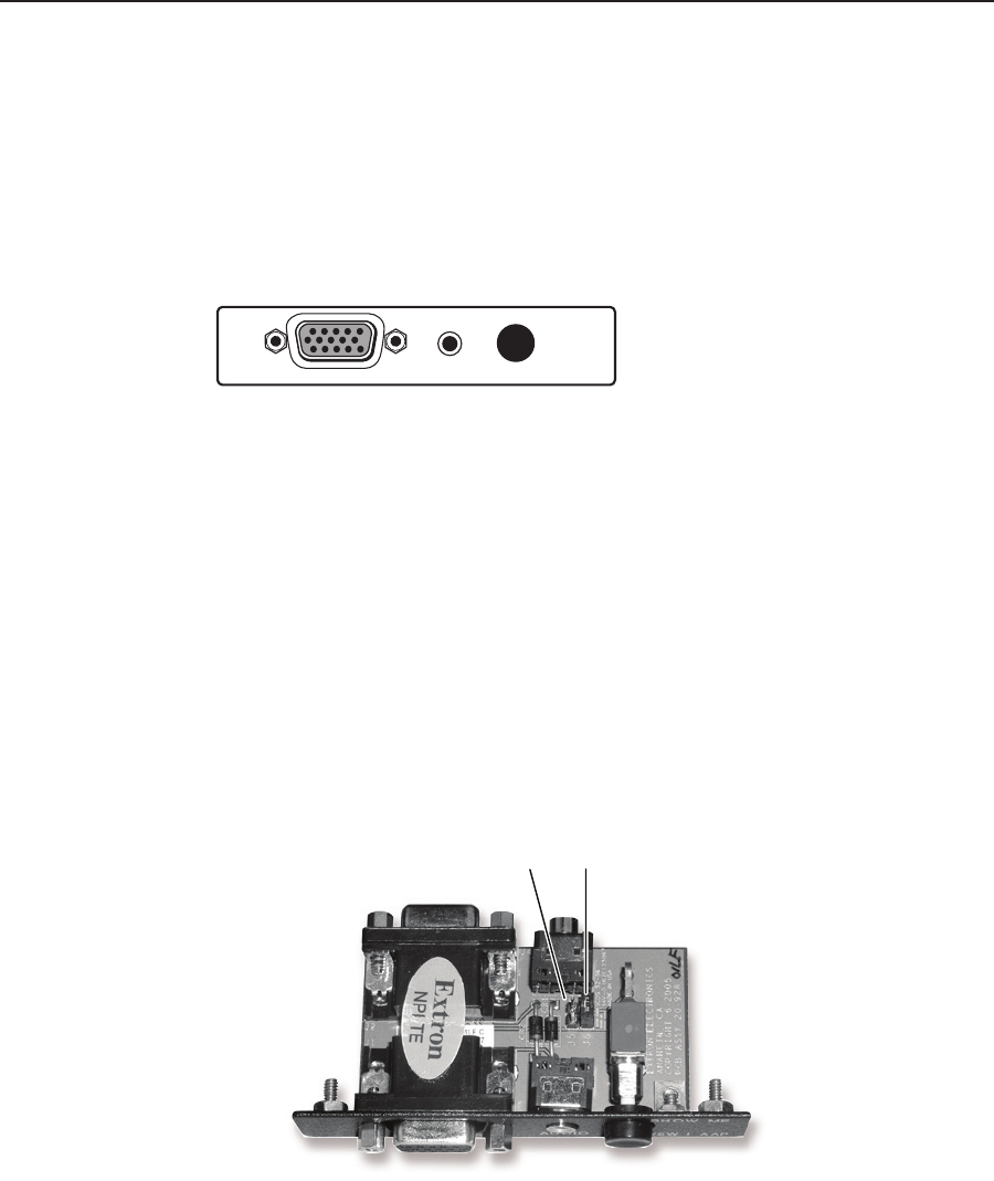
To use a VSW I AAP with a switcher:
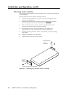
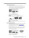
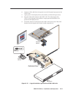
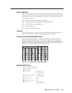
1
. ConrmthatjumperJ5isremovedandjumperJ6isinplaceonthe
VSW I AAP’s printed circuit board.
J5 J6
Figure 2-14 — VSW I AAP jumpers
2. Apply power to the switcher.
3. Connect a host computer to the switcher’s RS-232 control port.
4. Open a hyperterminal session on the host computer, and use a Simple
Instruction Set (SIS
™
) command to configure the switcher to operate with a
VSWIAAP(seechapter3,“OperationandControl”).
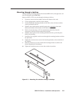
5. ConnectaVGAcablefromtheVSWIAAP’soutputconnectortooneofthe
switcher’s input ports.