


SW VGArs / Ars Series Switchers • Installation
Installation, cont’d
SW VGArs / Ars Series Switchers
3
Chapter Three
Operation
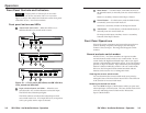
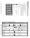
Front Panel Controls and Indicators
Front Panel Operations
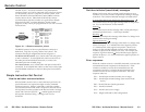
Configuring the switcher
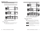
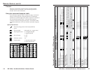
There are six jumpers on the circuit board, numbered JMP5,
JMP7, JMP9, JMP11, JMP 13, and JMP15, that control connection
with one or more VSW I AAP control panels (figure 2-9 and
figure 2-10).
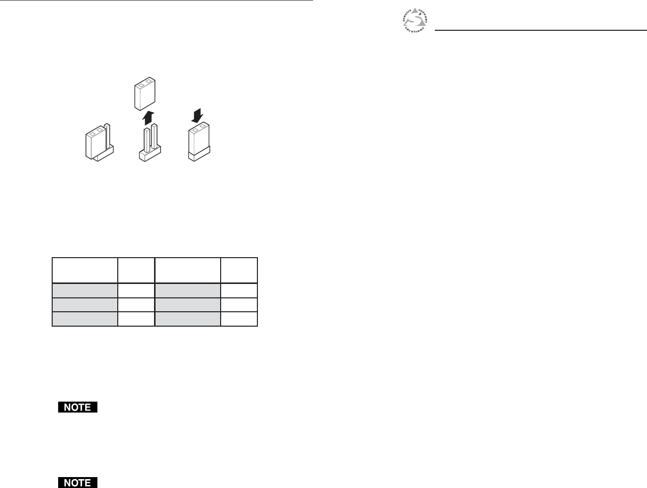
OPEN CLOSED
All jumpers are set open (removed) by default.
The jumpers in the table below must be set closed
(installed) when a VSW I AAP is connected to the
associated input.
Close the indicated jumpers in the table below
to adjust the appropriate settings.
Jumper
Input 1
Input 2
Input 3
JMP5
JMP7
JMP9
Jumper
VSW I AAP
connected to:
VSW I AAP
connected to:
Input 4
Input 5
Input 6
JMP11
JMP13
JMP15
Figure 2-10 — Jumper positions vs. VSW I AAP
input connections
These jumpers enable/disable VGA connector pin 5 (control) for
each input. Close (install) the jumper for a specific VGA input
to allow the VSW I AAP’s “show me” signal to select that input.
When an input is not connected via a VSW I AAP, that
input’s jumper should be in the default (open) position.
Each jumper, when closed (installed) allows the switcher to
receive the “show me” signal from the VSW I AAP on that
input’s VGA connector. When a jumper is open (removed) that
input cannot receive the signal.
Auto switch mode must be disabled when using the
switcher with one or more VSW I AAP remote controls.
If the auto switch mode is enabled, the input cannot be
selected using the “show me” function.
2-12