


SW VGArs / Ars Series Switchers • Installation
SW VGArs / Ars Series Switchers • Installation
Installation
2-3
Mounting the Switcher
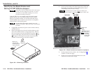
If you are going to connect VSW I AAP remote controls
to one or more inputs, identify the version of the
SW VGArs / Ars circuit board (to ensure that the
VSW I AAPs will work with this version) and configure
the switchers’ jumpers before mounting the
switcher. See “Identifying the Board Version and
Setting the SW VGA/Ars Jumpers” on page 2-10.
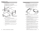
Rack mounting
UL guidelines
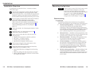
The following Underwriters Laboratories (UL) guidelines
pertain to the installation of the switcher into a rack (figure 2-1).
1. Elevated operating ambient — If installed in a closed or
multi-unit rack assembly, the operating ambient
temperature of the rack environment may be greater than
room ambient. Therefore, consider installing the equipment
in an environment compatible with the maximum 122 °F
(50 °C) ambient temperature (Tma) specified by Extron.
2. Reduced air flow — Installation of the equipment in a rack
should be such that the amount of air flow required for safe
operation of the equipment is not compromised.
3. Mechanical loading — Mounting of the equipment in the
rack should be such that a hazardous condition is not
achieved due to uneven mechanical loading.
4. Circuit overloading — Consideration should be given to
the connection of the equipment to the supply circuit and
the effect that overloading of the circuits might have on
overcurrent protection and supply wiring. Appropriate
consideration of equipment nameplate ratings should be
used when addressing this concern.
5. Reliable earthing (grounding) — Reliable earthing of rack-
mounted equipment should be maintained. Particular
attention should be given to supply connections other than
direct connections to the branch circuit (such as the use of
power strips).
Installation Overview
To install and set up the SW VGArs / Ars Series switchers,
follow these steps:
1
Turn all of the equipment off. Ensure that the video and
audio sources (computers, stereos, tape decks or other
devices), the SW VGArs / Ars switcher, the output devices
(projectors, speakers), and contact closure control device
are all turned off and disconnected from the power source.
2
If you are going to connect VSW I AAP remote controls to
one or more inputs, identify the version of the
SW VGArs / Ars circuit board (to ensure that the
VSW I AAPs will work with this version) and configure
the switcher’s jumpers. See “Identifying the Board
Version and Setting the SW VGA/Ars Jumpers” on
page 2-10.
3
Mount the switcher. See “Mounting the Switcher” on the
next page.
4
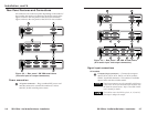
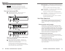
Attach the cables. See “Rear Panel Features and
Connections” later in this chapter.
5
Connect power cords and turn on the devices in the
following order:
• Output devices (projectors, monitors, speakers)
• SW VGArs / Ars Series switcher
• Contact closure/RS-232 controller
• Input devices (computers, audio sources)
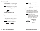
6
Select an input using the front panel buttons, or the
contact closure or RS-232 controller.
7
The picture should now appear and sound should be
audible (SW VGA Ars models). If not:
• Ensure that all devices are plugged in and receiving
power.
• Check the cabling and make adjustments as needed.
• Select a different input that is known to work to check
for a display and sound.
2-2