


SW VGArs / Ars Series Switchers • Remote Control
SW VGArs / Ars Series Switchers • Remote Control
Remote Control
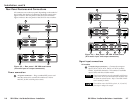
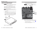
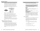
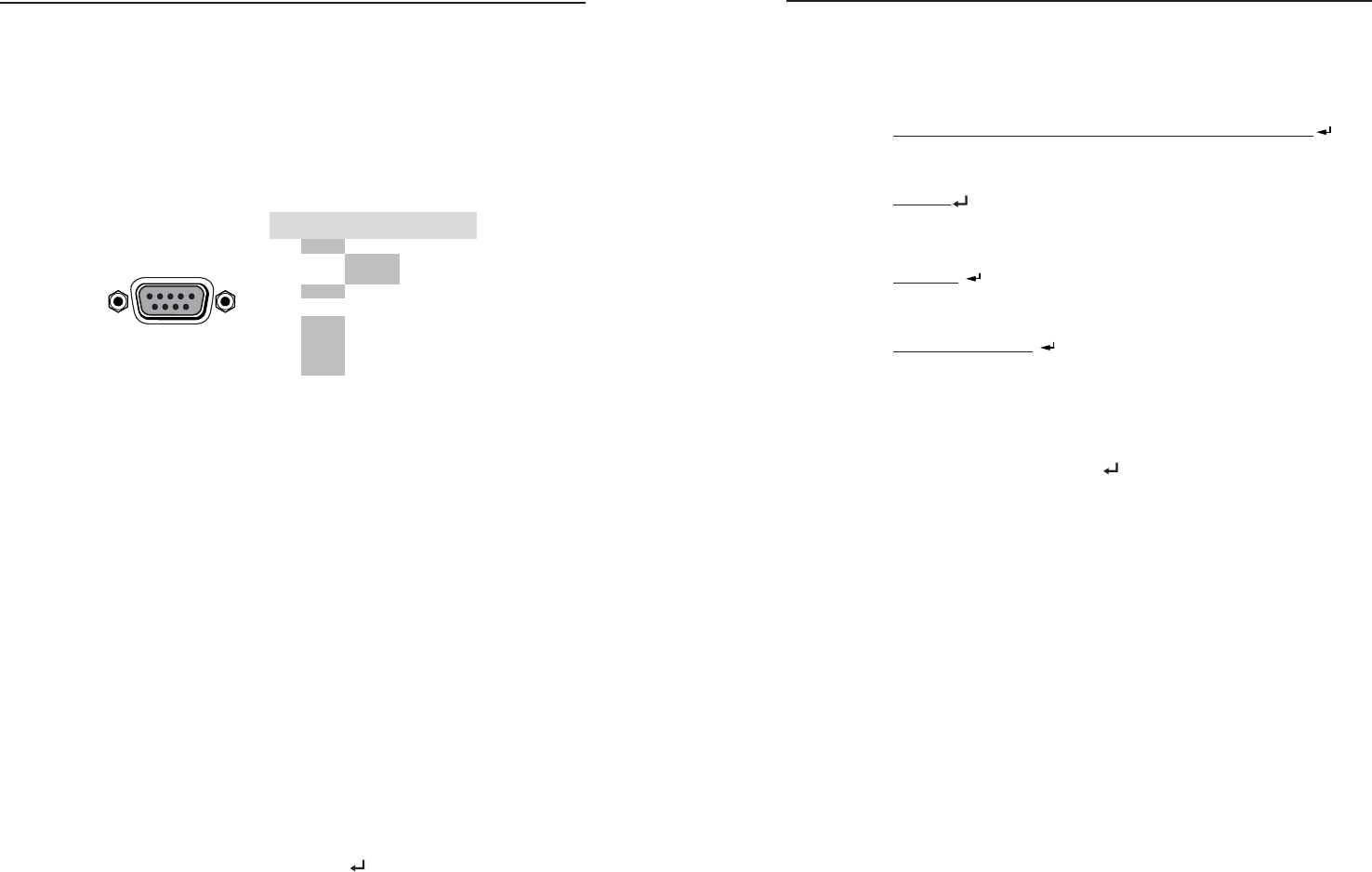
The SW VGArs / Ars Series switcher’s rear panel Remote
connector (figure 4-1) can be connected to the serial port output
of a host device, such as a computer or control system, to an
Extron IR 102 Kit Universal Remote Control, OR to a remote
contact closure device. Other than the IR 102 Kit, remote
communications with the switcher are via the Extron Simple
Instruction Set (SIS
™
) or under Windows
®
-based control
program; or they can be pin-programmed for use with a contact
closure device.
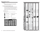
REMOTE
PIN
RS-232
Contact
Closure
Function
1
— In #1 Input #1
Input #2
Input #3
Input #4
Input #5
Input #6
2
TX — Transmit data
3
RX — Receive data
4
— In #2
5
Gnd Gnd Ground
6
— In #3
7
— In #4
8
— In #5
9
— In #6
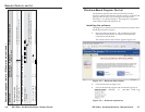
Figure 4-1 — Remote connector pinout
The RS-232 protocol of the rear panel Remote connector is
9600 baud, 1 stop bit, no parity, and no flow control. The
connector has the pin assignments shown in figure 4-1.
For RS-232 and IR control, use a control cable with only pins 2,
3, and 5 connected. To accomplish this, either cut the wires to
the other pins in hard-shelled connectors, or remove the
unneeded pins from molded plugs.
For contact closure, use a control cable with pins 2 and 3 NOT
connected. To accomplish this, either cut the wires to these pins
in hard-shelled connectors or remove these pins from molded
plugs.
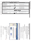
Simple Instruction Set Control
Host-to-switcher communications
SIS commands consist of one or more characters per field. No
special characters are required to begin or end a command
character sequence. When a command is valid, the switcher
executes the command and sends a response to the host device.
All responses from the switcher to the host end with a carriage
return and a line feed (CR/LF = ), which signals the end of
the response character string. A string is one or more
characters.
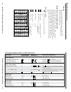
Switcher-initiated (unsolicited) messages
When a local event, such as a front panel operation or error
condition, occurs, the switcher responds by sending a message
to the host. The switcher-initiated messages are listed below:
(C) Copyright 2002, Extron Electronics SWy VGArs, Vx.xx
The switcher issues the copyright message when it first powers
on. Vx.xx is the firmware version number.
Inn•All
The switcher issues the Inn message when a front panel input
selection operation occurs. n is the input number.
Reconfig
The switcher initiates this message when there is a change in an
audio model’s audio gain setting.
Sig•n•n•n•n•n•n
The switcher initiates this message when there is a change in the
status of an input. n = 1 indicates the video signal is present,
n = 0 indicates the video signal is not present. There are as
many ns in the switcher-initiated message as the maximum
number of inputs for the models (2, 4, or 6). For example, the
response Sig•1•1•1•0•1•0 shows that the input signal is
present on inputs 1, 2, 3, and 5, and that no signal is present on
inputs 4 and 6.
Error responses
When the switcher receives a valid SIS command, it executes the
command and sends a response to the host device. If the
switcher is unable to execute the command because the
command is invalid or it contains invalid parameters, the
switcher returns an error response to the host. The error
response codes are:
E01 — Invalid input channel number (out of range)
E06 — Invalid input channel change (auto-switch mode
active)
E09 — Invalid function (mode) parameter
E10 — Invalid command
E13 — Invalid value (out of range)
E14 — Illegal command for this configuration
4-2 4-3