


SW VGArs / Ars Series Switchers • Installation
SW VGArs / Ars Series Switchers • Installation
Installation, cont’d
Installation instructions
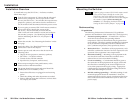
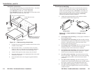
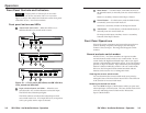
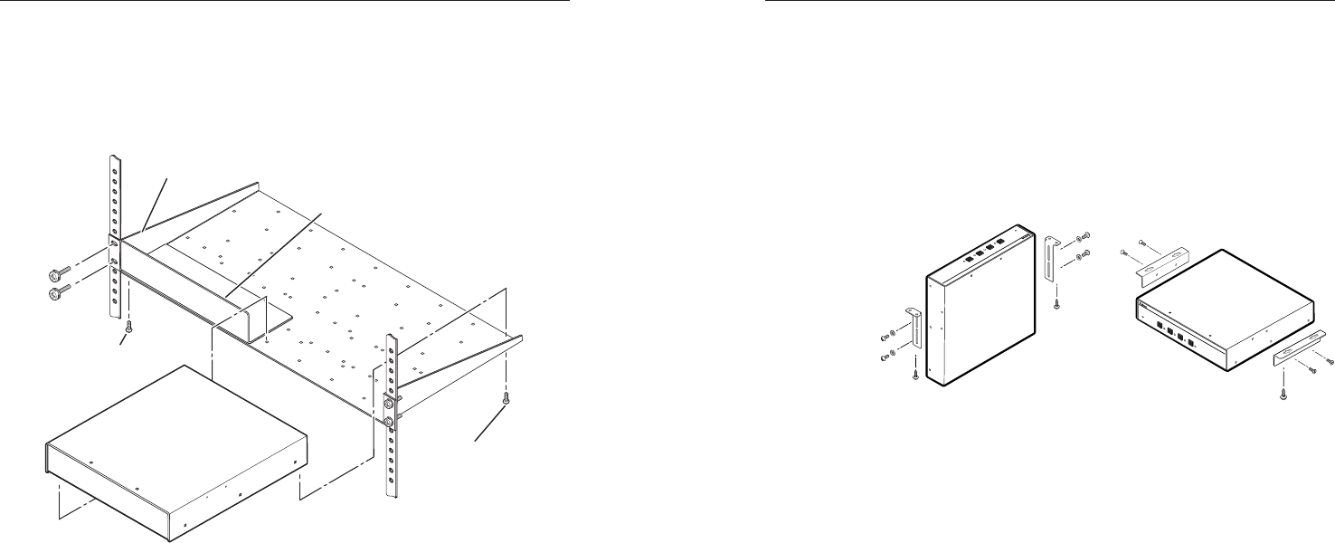
For optional rack mounting, mount the SW VGArs / Ars Series
on an optional RSU 129 1U Universal Rack Shelf
(part #60-190-01) or RSB 129 1U Basic Rack Shelf
(part #60-604-01) (figure 2-1). The switcher mounts either to the
right or to the left at the front of the rack.
Use 2 mounting holes on
opposite corners.
(2) 4-40 x 3/16"
Screws
NOTE: Using screws longer
than 3/16” will damage the
unit and void the warranty.
RSU 129 1U Universal Rack Shelf
Front false
faceplate
uses 2
screws.
1/2 Rack Width Front False
Faceplate
Figure 2-1 — Rack-mounting the switcher
1. If rubber feet were previously installed on the bottom of the
switcher, remove them.
2. Mount the SW VGArs / Ars Switcher on the rack shelf,
using two 4-40 x 3/16-inch screws in opposite (diagonal)
corners to secure the switcher to the shelf (figure 2-1).
3. Attach a blank panel or other unit(s) to the rack shelf.
4. Insert the shelf into the rack, aligning the holes in the shelf
with those of the rack.
5. Secure the shelf to the rack using the supplied machine
screws.
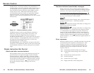
Furniture mounting
All of the switcher models can be mounted under furniture,
such as a table or podium surface, using optional MBU 125
under-desk mounting brackets (#70-077-01). All models can
also be mounted through a table or podium, using optional
MBD 129 through-desk mounting brackets (#70-077-02).
Furniture mount the switcher as follows:
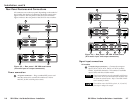
1. Attach the mounting brackets to the switcher with the
provided machine screws (figure 2-2).
Under Desk KitThrough Desk Kit
SW VGA/Ars SERIES
VGA/AUDIO SW
ITCHER
4
3
2
1
M
O
D
E
N
O
R
M
A
L
A
U
T
O
A
U
T
O
S
W
IC
H
A
C
T
IV
E
SW VGA/Ars SERIES
VGA/AUDIO SWITCHER
4
3
2
1
MODE
NORMAL
AUTO
AUTO SWICH
ACTIVE
Figure 2-2 — Under surface or through surface
mounting
2. For through-surface mounting, cut the proper sized hole in
the mounting surface.
3. For through-surface mounting, hold the switcher with the
attached brackets against the underside of the table or other
furniture. Mark the location of the screw holes of the
bracket on the mounting surface.
4. For through-surface mounting, drill four 3/32-inch (2 mm)
diameter pilot holes, 1/4 inch (6.3 mm) deep in the
mounting surface at the marked screw locations.
5. For through-surface mounting, insert four #8 wood screws
through the bracket and into the four pilot holes. Tighten
all four screws to secure the switcher in place.
6. For under-surface mounting, insert #8 wood screws into
the four pilot holes. Tighten each screw into the mounting
surface until just less than 1/4 inch of the screw head
protrudes.
7. For under-surface mounting, align the mounting screws
with the slots in the brackets and place the switcher against
the surface, with the screws through the bracket slots.
8. For under-surface mounting, slide the switcher slightly
forward or back, then tighten all four screws to secure the
switcher in place.
2-4
2-5