


SWP123 Presentation Switcher • Installation
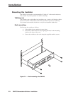
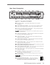
Installation, cont’d
2-6
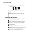
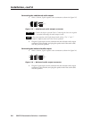
Connecting the unbalanced audio output
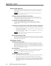
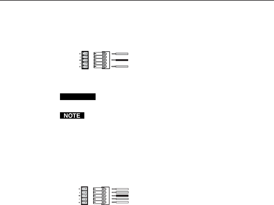
1. Wire a 3.8 mm, 5-pole captive screw connector as shown in figure 2-5.
Figure 2-5 — Unbalanced audio output connector
CAUTION
Connect the sleeve to ground (Gnd). Connecting the sleeve to a negative
(-) terminal will damage the audio output circuits.
Pay extra attention to the Right channel audio wiring. The “+” and “-”
layout is different from most other Extron products.
2. Plug the 5-pole captive screw connector into the selected audio output
connector of the switcher, and plug the speaker end of the audio cable
into the powered speakers.
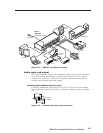
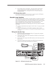
Connecting the balanced audio output
1. Wire a 3.8 mm, 5-pole captive screw connector as shown in figure 2-6.
Figure 2-6 — Balanced audio output connector
2. Plug the 5-pole captive screw connector into the selected audio output
connector of the switcher, and plug the speaker end of the audio cable
into the speakers.
Tip
Ring
Sleeve (s)
Tip
Ring
OUT
LR
Tip
See Caution
Sleeve (s)
Tip
See Caution
LR
OUT