


SWP123 Presentation Switcher • Quick Start
QS-1
Quick Start — SWP123
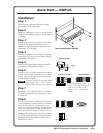
Installation
Step 1
Turn off power to the switcher and all other
devices that will be connected.
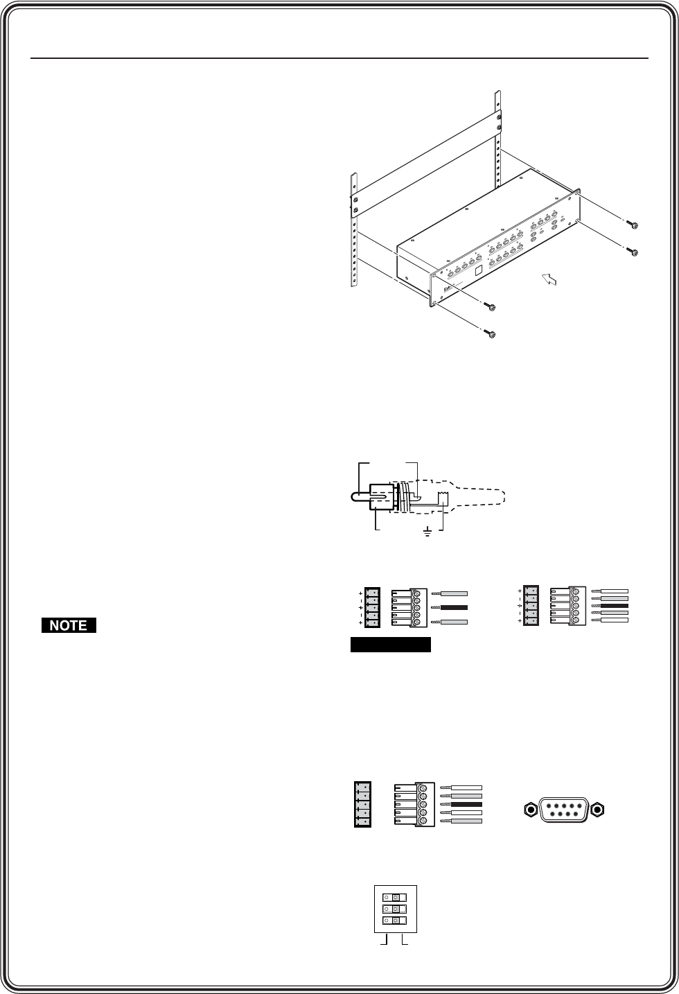
Step 2
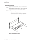
Mount the switcher in a rack, or install the four
rubber feet (included) and place the switcher on
a desktop.
Step 3
Attach VGA, S-video, or composite video input
devices to the designated groups on the
switcher, using appropriate connectors (see
illustration on next page).
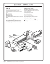
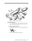
Step 4
Connect up to three VGA, S-video, or composite
video output devices to the switcher, using the
appropriate connections.
Step 5
Attach audio inputs to the switcher with RCA
connectors (see illustration at right).
Step 6
Connect up to four audio output devices to the
switcher (one to each group and one to Master
Audio) using 5-pole captive screw connectors
(see illustration at right).
Pay extra attention to the Right channel
audio wiring. The “+” and “-” layout is
different than most other Extron products.
Step 7
Set the Mic “+24V Phantom Power” switch to
match the microphone type, then plug in the
microphone.
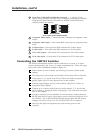
Step 8
If the switcher is to be connected to a computer
or host controller for remote control, connect the
host’s RS-232 cable to a 5-pole captive screw
connector and to the serial port on the switcher
(see wiring illustration at right and the serial
port pinout table in chapter 5, Remote Control).
Configure the serial port for the type of control
you will be using (RS-232, RS-422, or RS-485) by
setting the DIP switch adjacent to the port (see
illustration at right ).
Rack mounting the SWP123
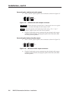
CAUTION
Connect the sleeve to ground
(Gnd). Connecting the sleeve to a
negative (-) terminal will
damage the audio output
circuits.
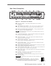
DB9 Pinout (Female)
51
96
Rx+
Rx-
Tx+
Tx-
Gnd
Rx+
Rx-
Tx+
Tx-
Gnd
RS-232/422-485
5-pole captive screw connector/socket
4
B
L
A
N
K
1
3
V
G
A
/
A
U
D
I
O
S
E
L
E
C
T
2
4
B
L
A
N
K
1
3
S
-V
ID
E
O
/
A
U
D
I
O
S
E
L
E
C
T
C
O
M
P
O
S
IT
E
V
ID
E
O
/
A
U
D
IO
S
E
L
E
C
T
2
V
G
A
V
O
L
U
M
E
M
U
T
E
M
IC
L
E
V
E
L
M
IC
R
O
P
H
O
N
E
T
A
L
K
O
V
E
R
S
-
V
ID
E
O
M
A
S
T
E
R
A
U
D
IO
S
E
L
E
C
T
V
ID
E
O
M
I
C
4
B
L
A
N
K
1
3
2
S
W
P
1
2
3
Presentation Switcher
Tip (+)
Sleeve ( )
Unbalanced Input
RS-232
RS-422/485
Balanced Output
Tip
Ring
Sleeve (s)
Tip
Ring
OUT
LR
Unbalanced Output
Tip
See Caution
Sleeve (s)
Tip
See Caution
LR
OUT