


Remote Control
SWP123 Presentation Switcher • Remote Control
5-2
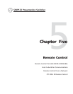
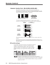
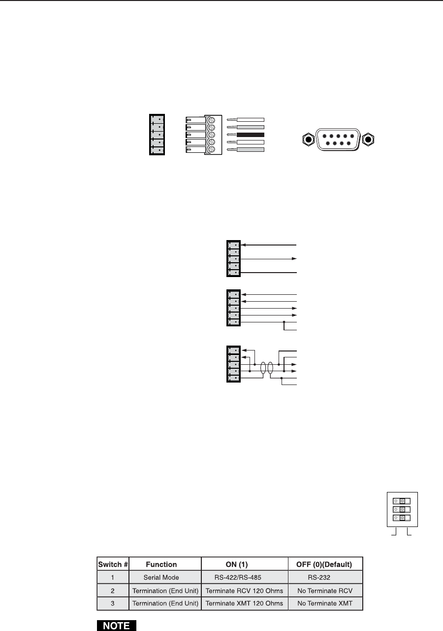
Remote Control Port (RS-232/RS-422/RS-485)
The SWP123 Presentation Switcher RS-232/RS-422/RS-485 port
connector is used to connect to a host or external controlling device, such
as a computer or control system, which can generate the proper command
codes and recognize the switcher’s responses.
The RS-232/RS-422/RS-485 connector is a 5-pole, captive screw
connector (see illustration above) with the following pin designations:
The default protocol is 9600 baud, 8-bit, 1 stop bit, no parity, and no flow
control.
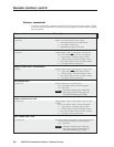
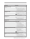
Commands and responses for programming the SWP123 Switcher from a
host system connected to the RS-232/RS-422/RS-485 port are listed on the
following pages.
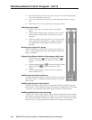
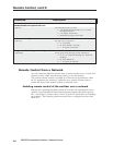
DIP switch settings
Use the DIP switch bank in the back of the SWP123 switcher to
configure the serial ports to operate as an RS-232 (factory
default) or RS-422/RS-485 interface. DIP switch settings
change according to the standard used. Configure the DIP
switch according to your requirements, based on the table
below.
Termination resistors should be turned on only when the switcher is
operating in RS-422/RS-485 mode, and then only for the first and last units
on a long serial line. The default switch settings are all OFF. In half-duplex
mode, turn on only one of the termination resistors, as they are connected
together by the cable.
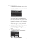
DB9 Pinout (Female)
To control equipment
51
96
Rx+
Rx-
Tx+
Tx-
Gnd
Rx+
Rx-
Tx+
Tx-
Gnd
RS-232/422/485
5-pole captive screw connector/socket
RS-232
RS-422/485
RX+
RX-
TX+
TX-
GND
2
3
5
RX
TX
GND
RX+
2
TX+
RX-
6
TX-
TX-
7
RX-
TX+
3
RX+
GND
5
GND
1
GND
1
GND
Switcher
Serial Port
Computer
DB-9 Serial Connector
RS-232
Connection
RS-422/485
Full Duplex
Connection
RS-485
Half Duplex
Connection
RX+
2
TX+
RX-
6
TX-
TX+
3
RX+
GND
5
GND
TX-
7
RX-