


TSC 100 • Serial Control
TSC 100 • Serial Control
Serial Control, cont’d
Programmer’s Guide for Serial Communication
The TSC 100 can be controlled by a host computer or other
control device via an RS-232/422 connection with the following
protocol:
• 9600 baud
• 1 stop bit
• no parity
• no flow control
The control device can use either Extron’s Simple Instruction
Set
™
(SIS
™
) or the Extron graphical control program for
Windows
®
.
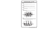
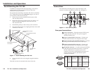
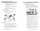
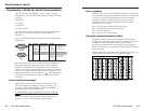
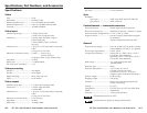
The rear panel RS-232 9-pin D connector has the following pin
assignments:
Female
51
96
Male
15
69
Pin RS-232RS-422Description
1
—
2Tx
Rx-
Tx-Transmit data
3
Rx Receive data
4
—
5
Gnd GndSignal ground
6
—
7
—
Rx+
8
—
Tx+
9
—
—
—
——
—
—
——
Description
Transmit data (-)
Receive data (-)
Signal ground
Receive data (+)
Transmit data (+)
—
—
—
—
—
—
SIS commands consist of one or more characters per field. No
special characters are required to begin or end a command
sequence. When the TSC 100 determines that a command is
valid, it executes the command and sends a response to the host
device. All responses from the TSC 100 to the host end with a
carriage return and a line feed (CR/LF = ), which signals the
end of the response character string. A string is one or more
characters.
Device-initiated messages
When a local event such as an input selection occurs, the
TSC 100 responds by sending a message to the host. No
response is required from the host. The device-initiated
message is shown below (underlined).
(C)COPYRIGHT 2002, EXTRON ELECTRONICS TSC 100,
Vx.xx
The device displays the copyright message when it first
powers on. Vx.xx is the firmware version number.
3-2
Error responses
When the TSC 100 receives a valid SIS command, it executes the
command and sends a response to the host device. If the device
is unable to execute the command because the command is
invalid or contains invalid parameters, it returns an error
response to the host. The error response codes and their
descriptions are as follows:
E01 — Invalid input channel number (too large)
E09 — Invalid function number (too large)
E10 — Invalid command
E13 — Invalid value (out of range)
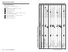
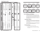
Using the command/response table
The table on page 3-4 lists the commands that the switcher
recognizes as valid, the responses that are returned to the host, a
description of the command’s function or the results of
executing the command, and an example of each command.
Lower case characters are acceptable in the command field only
where indicated.
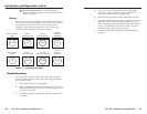
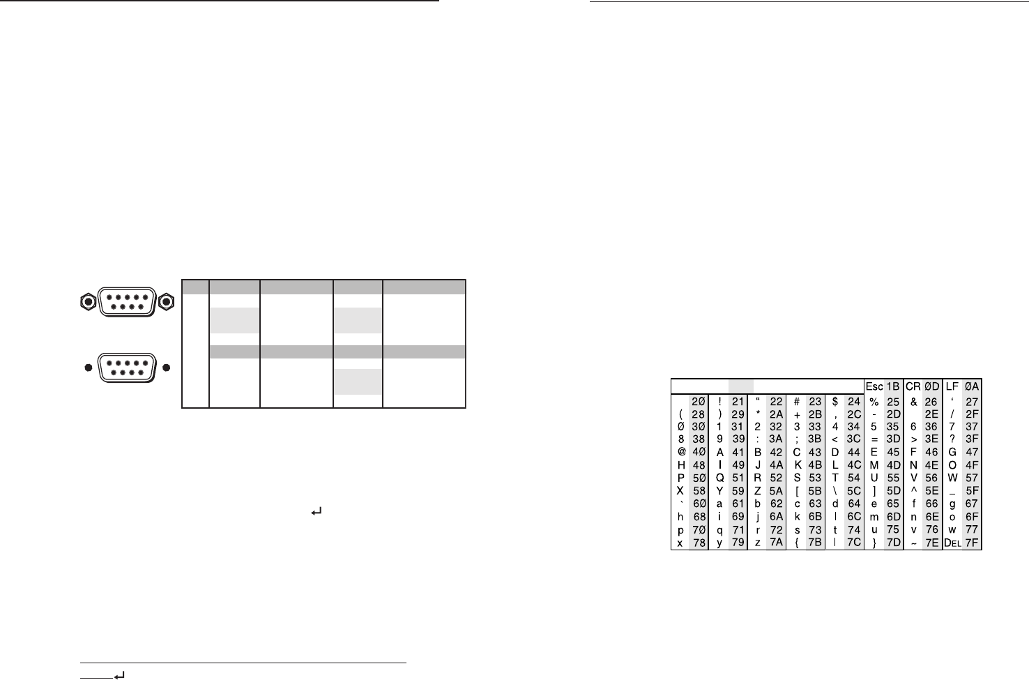
Symbol definitions are shown at the beginning of the table. An
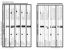
ASCII to HEX conversion table is provided in figure 6.
ASCII to HEX Conversion Table
•
Figure 6 — ASCII-to-HEX conversion table
3-3