


TSC 100 • Installation and Operation
TSC 100 • Installation and Operation
Installation and Operation, cont’d
2-52-4
Software for RS-232 or RS-422 control is included with the TSC
100. See chapter 3, Serial Control for details.
6
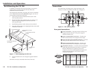
Buffered loopout composite BNC connector —
Connect one BNC female connector for buffered
composite loopout.
7
Buffered loopout S-video 4-pin mini-DIN connector
— Connect one 4-pin mini DIN connector for buffered
S-video loopout.
8
Output 4-pin S-video mini DIN connector — One
4-pin mini DIN connector for S-video output.
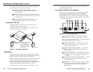
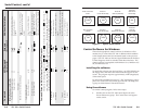
Cabling the TSC 100
Use high resolution cable for all video input and output
connections. Refer to the Appendix.
To cable the TSC 100, connect the input and output devices to
the device using figure 3 as a guide.
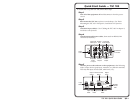
NTSC VCR
PAL VCR
User selects between S-video
or composite inputs and
between NTSC and PAL
outputs; selectable from
the front panel. Composite
input is shown.
Extron
TSC 100
NTSC Monitor
Buffered
Loop-Out
RS-232/422
COMPOSITE
COMPOSITE
S-VIDEO
S-VIDEO
1
2
POWER
I
N
P
U
T
S
O
U
T
P
U
T
S
12V
1A MAX
Figure 3 — Example application
Operation
Connect power cords and turn on the display output devices
(projectors, monitors, VCRs), interface, and input devices (DSS,
cable box, DVD). The system is ready for operation.
Select an input from the front panel button or the remote control
(RS-232). The image should now appear on screen. If not,
ensure that all devices are plugged in and receiving power.
Check the cabling and button settings, and make adjustments as
needed. Select a different input to check for a picture.
If problems persist, see Troubleshooting in this chapter. If the
troubleshooting tips do not help, call the Extron S
3
Sales &
Technical Support Hotline.
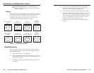
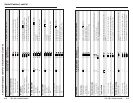
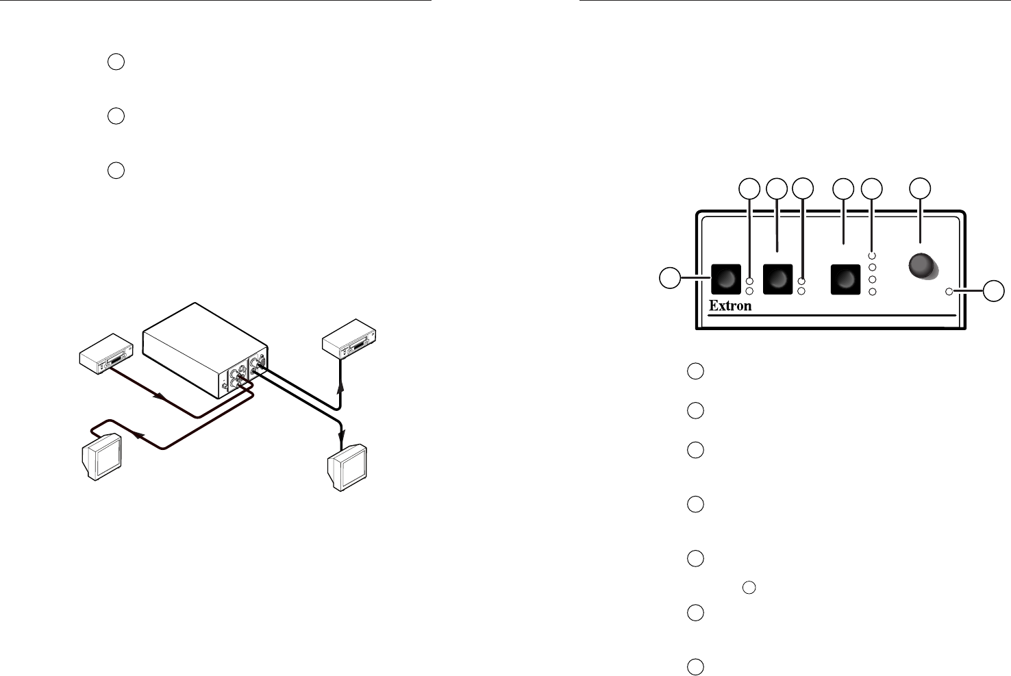
Front panel controls and indicators
The TSC 100’s controls and indicators are located on the front
panel (figure 4). Push buttons are used to select the input
source, output standard, and picture controls (Color, Tint,
Bright, and Contrast), and LEDs indicate the options selected.
An Adjust knob is provided to make adjustments to the picture
control element selected.
TSC 100
TRANSCODING STANDARDS CONVERTER
1
2
NTSC
COLOR
TINT
BRIGHT
CONTRAST
PAL
MAX
MIN/
ADJUST
INPUT OUTPUT
PICTURE
CONTROLS
1
2
8
3
4
5
6
7
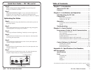
Figure 4 — TSC 100 front panel
1
Input selector button — Press this button to select
between input 1 (composite) and input 2 (S-video).
2
Input selection indicator LEDs — A green LED lights
to indicate which input is selected.
3
Output selector button — Press this button to select
between NTSC or PAL output on the composite or
S-video output connectors.
4
Output selection indicator LEDs — A yellow LED
lights to indicate which standard output (NTSC or
PAL) is selected.
5
Picture Controls button — Press this button to select
the element of the picture to be adjusted by the Adjust
knob
7
(either Color, Tint, Bright, or Contrast).
6
Picture Controls selection indicator LEDs — A yellow
LED lights to indicate the element of the picture
selected for adjustment.
7
Adjust knob — Rotate this knob to adjust the element
of the picture selected by the Picture Controls button
and indicated by the Picture Controls selection
indicator LED.