


TSC 100 • Installation and Operation
TSC 100 • Installation and Operation
Installation and Operation
2-3
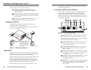
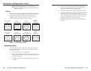
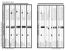
Connections
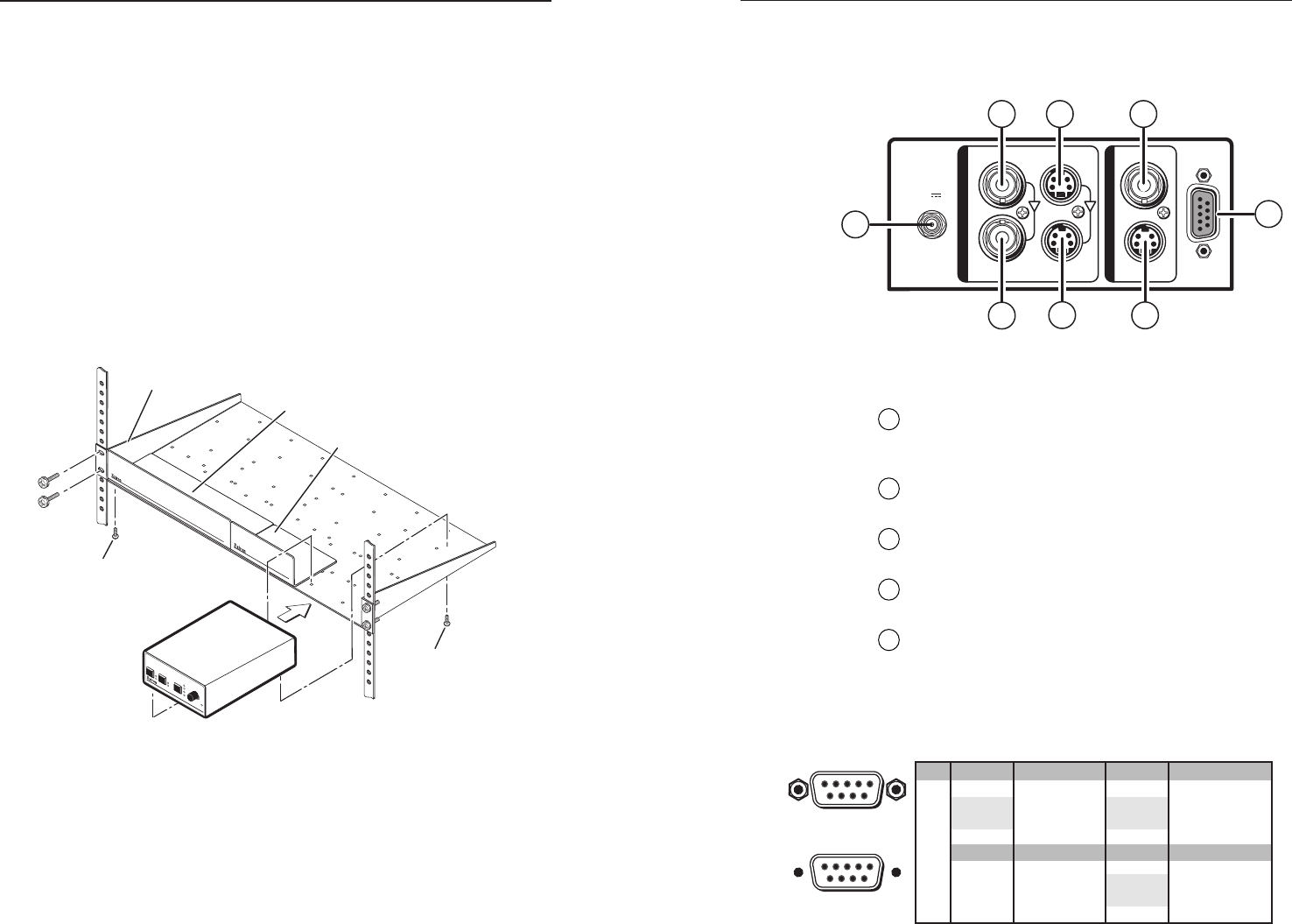
All connections, including power, input and output, and
control, are on the rear panel of the TSC 100. See figure 2.
RS-232/422
COMPOSITE
COMPOSITE
S-VIDEO S-VIDEO
1
2
POWER
I
N
P
U
T
S
O
U
T
P
U
T
S
9 V
1A MAX
8
6
1
2
3
4
5
7
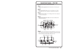
Figure 2 — TSC 100 rear panel
Rear panel connections
1
Power connection — Plug the external 9 VDC power
supply into this connector. The power supply is
included with the unit.
2
Input 1 composite BNC connector — Connect one
BNC female connector for composite video input.
3
Input 2 S-video 4-pin mini DIN connector — Connect
one 4-pin mini DIN connector for S-video input.
4
Output composite BNC connector — Connect one
BNC female connector for composite video output.
5
RS-232/422 connector — Use this connector for RS-232
or RS-422 communications and control. Connect an
RS-232 or RS-422 device (control system or PC
computer) for remote switching between inputs and
remote centering control to this female 9-pin D
connector (see below).
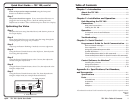
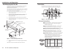
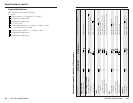
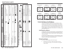
Rack Mounting the TSC 100
In addition to using the TSC 100 on a desktop, it can also be
rack mounted. To rack mount the TSC 100, follow the
installation instructions below.
For optional rack mounting, mount the TSC 100 on a standard,
19" 1U Rack Shelf (Extron part #60-190-01) (figure 1) in one of
four locations on the front of the rack.
1. If feet were previously installed on the bottom of the
TSC 100, remove them.
2. Mount the TSC on the rack shelf using two 4-40 x 3/16”
screws in opposite (diagonal) corners to secure the
TSC 100 to the shelf.
3. Install blank panel(s) or other unit(s) to the rack shelf.
4. Insert the shelf into the rack, aligning the holes in the shelf
with those of the rack.
Use 2 mounting holes on
opposite corners.
(2) 4-40 x 3/16"
Screws
1U Universal Rack Shelf
Both front false faceplates
use 2 screws.
1/4 Rack Width Front False
Faceplate
1/2 Rack Width Front False
Faceplate
TSC 100
TRAN
SCODING STAN
DAR
DS CONV
ERT
ER
1
2
NTSC
COLOR
TIN
T
BRIGHT
CONT
RAST
PAL
MAX
MIN/
ADJ
UST
INPUT OUTPUT
PICTURE
CONTROLS
Figure 1 — Rack mounting the TSC 100
5. Secure the shelf to the rack using the supplied machine
screws.
This shelf can only be mounted in the front of the rack.
2-2
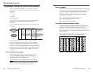
Female
51
96
Male
15
69
Pin RS-232RS-422Description
1
—
2Tx
Rx-
Tx-Transmit data
3
Rx Receive data
4
—
5
Gnd GndSignal ground
6
—
7
—
Rx+
8
—
Tx+
9
—
—
—
——
—
—
——
Description
Transmit data (-)
Receive data (-)
Signal ground
Receive data (+)
Transmit data (+)
—
—
—
—
—
—