


2
Hardware Included in the Kit
Parts Qty Application
¼ - 20 x 2 inch, pan head bolts, 4 Base plate to wall installation
¼ inch Toggle assembly 4 Base plate to wall installation
¼ inch metal washers (47/64 inch OD) 8 Base plate to wall installation
5/16 x 3 inch lag screws 4 Base plate to wall installation
5/16 inch metal washers (11/32 inch ID, 11/16 inch OD) 4 Base plate to wall installation and boom arm
¼-28 x 3/4 inch screw 1 Securing boom arm (top)
¼-20 x 1/2 inch button screws 4 Securing boom arm (extension)
10-32 x 3/8 inch pan head screws 2 Securing boom arm (bottom)
10-32 x ¼ inch set screw, 1 Securing projector pipe
USFM 100 Installation Guide, cont'd
6-32 x ¼ inch button screws 11 Securing covers for boom arm (10)
Securing device mounting plate (1)
6-32 x ½ inch button screws 4 Securing plastic covers for enclosure
Tie wraps 4 Securing power supply wires
4-40 x ¼ inch pan head screws 2 Securing switcher to plate
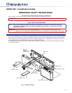
Installation
WARNING: Risk of Personal Injury and property damage. Before commencing installation, the wall structure
must be examined to determine if it is suitable for the proper installation and support of this
product. If needed, the installer should reinforce the wall. Drywalls should have a minimum
thickness of 1/2 inch and a maximum thickness of 5/8 inch. Improper installation of this product
could lead to serious injury.
The location and type of wall where the USFM 100 is to be installed should be identified before starting
installation. This determines the installation method and the type of fasteners used to secure the plate to the wall.
Recommended Installation Tools
• Level (24 inch) • Ladder • Tape measure • Stud nder • Drill and drill bits • Phillips screwdriver
• Allen hex wrench (5/64 size)
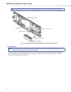
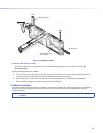
1. Mount the Base Plate
NOTE: Before installation, see the user manual for the display device to determine the proper location and
placement of the mount. Take into consideration the projector lens offset, screen size, screen aspect, and
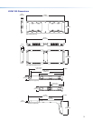
projected image throw distance. See page 8 for the dimensions of the USFM 100 (with the projector pipe
and UPB 25 attached) to aid in this determination
a. At the desired site, use an edge-to-edge stud finder to locate the center of the wall studs (wood or steel).
Mark each stud location. Minimum joist size should be 2 inches by 4 inches.
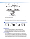
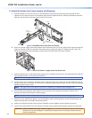
ATTENTION: Potential Damage to Property. For secure installation, it is required to attach the
base plate to two wall studs, using a minimum of four securing points. Drywall toggles
can be used for holes that are not aligned with studs (see figure 3). This product is not
intended to be mounted solely to drywall.
b. Hold and level the base plate against the wall. Mark a minimum of four positions (two top, two bottom)
using either the mounting slots or the keyholes (slots uppermost) that are on the stud lines (see the + marks
in figure 2). Where applicable, mark the mounting holes on the wall for drywall toggles.