


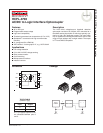
HCPL-3700 AC/DC to Logic Interface Optocoupler
©2005 Fairchild Semiconductor Corporation www.fairchildsemi.com
HCPL-3700 Rev. 1.0.1 2
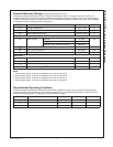
Absolute Maximum Ratings
(No derating required up to 70°C)
Stresses exceeding the absolute maximum ratings may damage the device. The device may not function or be
operable above the recommended operating conditions and stressing the parts to these levels is not recommended.
In addition, extended exposure to stresses above the recommended operating conditions may affect device reliability.
The absolute maximum ratings are stress ratings only.
Notes:
1. Derate linearly above 70°C free-air temperature at a rate of 1.8 mW/°C.
2. Derate linearly above 70°C free-air temperature at a rate of 2.5 mW/°C.
3. Derate linearly above 70°C free-air temperature at a rate of 0.6 mA/°C.
4. Derate linearly above 70°C free-air temperature at a rate of 1.9 mW/°C.
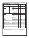
Recommended Operating Conditions
The Recommended Operating Conditions table defines the conditions for actual device operation. Recommended
operating conditions are specified to ensure optimal performance to the datasheet specifications. Fairchild does not
recommend exceeding them or designing to absolute maximum ratings.
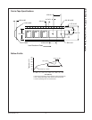
Symbol Parameter Value Units
T
STG
Storage Temperature -55 to +125 °C
T
OPR
Operating Temperature -40 to +85 °C
T
SOL
Lead Solder Temperature 260 for 10 sec °C
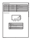
EMITTER
I
IN
Input Current Average 50 (Max.) mA
Surge, 3ms, 120Hz Pulse Rate 140 (Max.)
Transient, 10µs, 120Hz Pulse Rate 500 (Max.)
V
IN
Input Voltage (Pins 2-3) -0.5 (Max.) V
P
IN
Input Power Dissipation
(1)
230 (Max.) mW
P
T
Total Package Power Dissipation
(2)
305 (Max.) mW
DETECTOR
I
O
Output Current (Average)
(3)
30 (Max.) mA
V
CC
Supply Voltage (Pins 8-5) -0.5 to 20 V
V
O
Output Voltage (Pins 6-5) -0.5 to 20 V
P
O
Output Power Dissipation
(4)
210 (Max.) mW
Symbol Parameter Min. Max. Units
V
CC
Supply Voltage 2 18 V
T
A
Operating Temperature 0 70 °C
f Operating Frequency 0 4 kHz