


Page 9
Faria
®
Serial Bus Installation and Wiring Guide
The system consists of:
• One Gateway box to interface with the engine and external senders and sensors.
• One 4” Tachometer with Fuel Monitor
• Various 2” instruments, including but not limited to
• Voltmeter
• Oil Pressure gauge
• Engine Temperature gauge
• Fuel Level gauge
• Transmission Temperature
Installation
Installation of the Fari
®
Serial Bus system is accomplished as follows:
Gateway Box
The Gateway
™
box is the central unit of the system. As all of the senders and other
information source peripherals connect to the Gateway
™,
the Gateway
™
box should be
mounted in a protected area in the best location to provide the maximum cabling benefit.
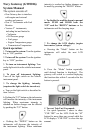
The Gateway
™
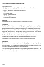
box power cable must be installed to allow connection to “battery positive”
(always on), “battery negative” (ground), and a source of “switched power” which turns on
with the engine ignition switch (see Figure 2 and Table 1).
The “Faria
®
Bus” cable must be routed from the Gateway
™
box to the instrument panel area
to connect the instruments to the data bus and instrument power (see Figure 3).
The remainder of the connections to the Gateway
™
box are described below.
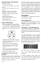
Instruments
The instruments are mounted using the provided back-clamps and mounting hardware.
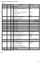
Each instrument comes with a bus connection cable (12”). The main “Faria
®
Bus” cable
from the Gateway
™
box is connected to the most convenient instrument using either of the
two four (4) pin connectors provided on the instrument case.
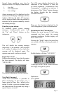
Each additional instrument is connected to the previous instrument using one of the 12” bus
connection cables. The cable may be connected to either of the two connectors provided on
the instrument case (see Figure 3).