


Gateway System Specifications:
Operation voltage:
+12 V DC or +24 V DC
+12 V DC (10 V DC (Min.) to 16 V DC
(max.))
+24 V DC (20 V DC (Min.) to 32 V DC
(max.))
Maximum Current with maximum
backlight: < 1500 mA @ 12 V DC
Minimum Current at switch off status:
< 10 mA @ 12 V
Operational temperature:
-40˚ F to 185˚ F (-40˚ C to 85˚ C)
Storage temperature:
-40˚ F to 185˚ F (-40˚ C to 85˚ C)
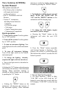
System Description
♦ There are three push buttons (Mode,
UP, and DOWN) for selecting different
message screens, changing the instrument
lighting intensity, disabling audible alarm,
etc.
♦ Audible and visual alarms. The LCD
will display Warning messages while an
audible “beep” occurs.
♦ The Gateway is environmentally
sealed, and is water resistant per SAE
J1960 paragraphs 4.6.2, 4.7.1.2 and
4.8.1.2.
♦ Faria
®
serial bus gauges/light arrays
can be connected up to 120 feet (40
meters) from the gateway box.
Turning the Gateway System
ON/OFF
When the “ignition” switch is turned to the
“on” position, the system is turned on. When
“ignition” switch is turned to the “off”
position, the system will turn off.
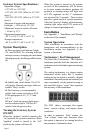
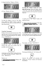
When the system is turned on, the pointer
on each of the instruments will be driven
to its most counter clockwise position, all
positions in warning arrays will light, and
all LCD segments on the 5” tachometer
are activated for 2 seconds. These actions
provide a quick check of system operation.
After this “boot-up” display, all instruments,
warning light arrays and LCD screen will
change to normal operating mode.
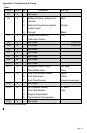
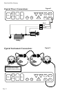
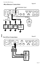
Installation
See Appendix 1: “Installation and Wiring”
at the end of this manual.
System Operation:
After installation in accordance with the
instructions and recommendations in the
Installation section (see Appendix 1), the
system is functional.
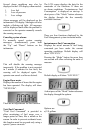
Tachometer / Fuel Management
The Serial Bus Tachometer / Fuel Monitor
instrument provides both the functions of a
tachometer and a fuel and engine monitoring
system.
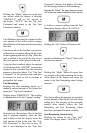
The analog tachometer is a stepper motor
instrument which looks like a standard
analog device but which is actually a digital
instrument. On small pointer movements you
may occasionally see the pointer moving in
the one-third degree “steps” that represent
the accuracy of the instrument.
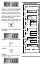
The LCD shows messages, like engine
hours, system voltage, and engine alarm
conditions.
In order to minimize “false” alarms, the
“low voltage” alarm only functions when
the engine is known to be running based on
the presence of tachometer data.
Page 3