


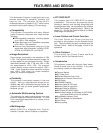
10
CONNECTING THE PROJECTOR
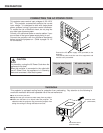
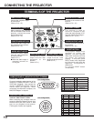
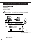
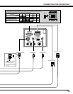
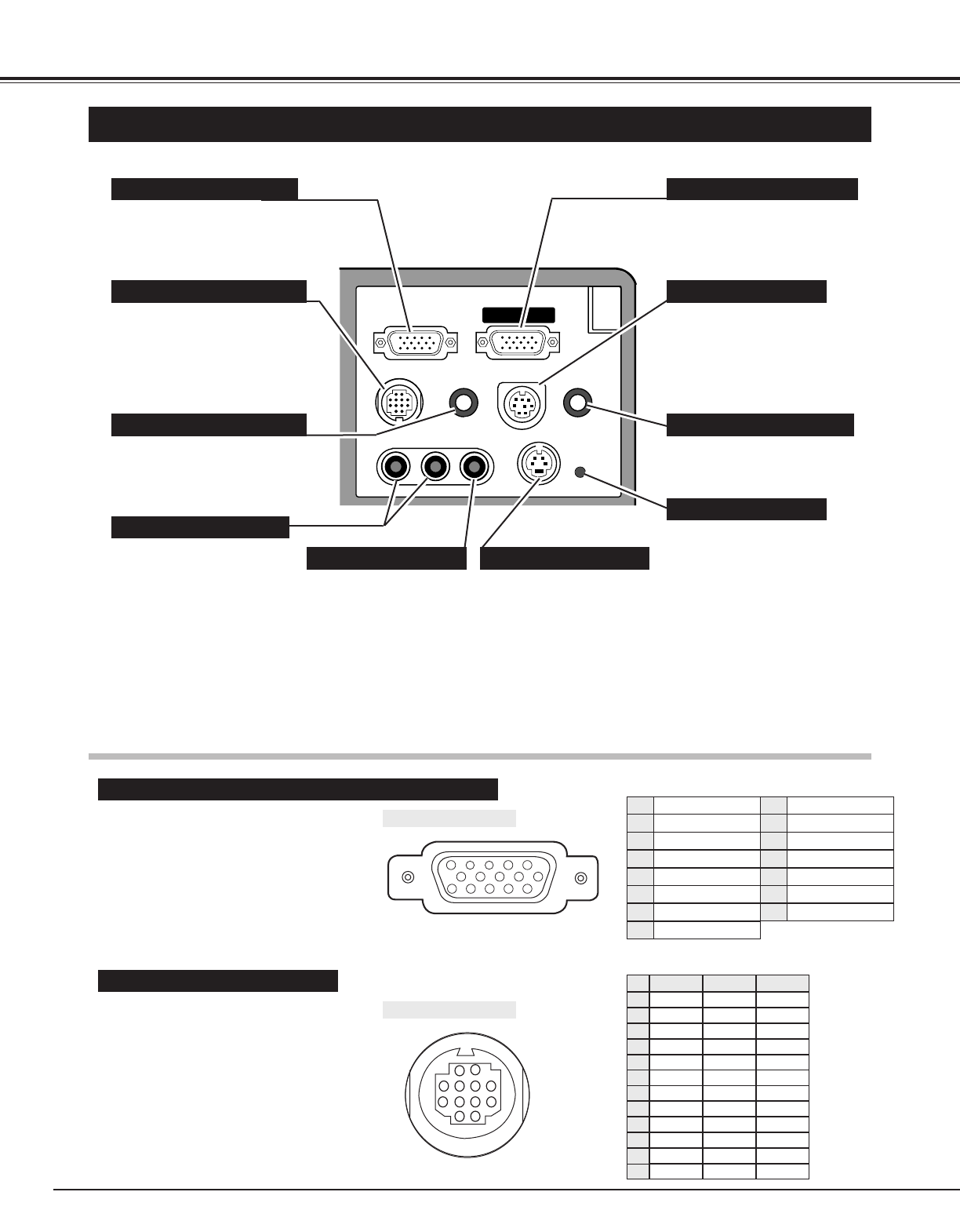
TERMINALS OF THE PROJECTOR
¥
COMPUTER IN
MONITOR OUT
CONTROL PORT
AUDIO IN
MCI SERIAL
AUDIO OUT
(MONO)
VIDEOR-AUDIO-L
S-VIDEO
Connect the computer output
to this terminal.
(Refer to P12 ~15.)
When controlling the computer
with the Remote Control of this
projector, connect the mouse
port to this terminal.
(Refer to P12 ~15.)
Connect to the monitor to this
terminal.
(Refer to P12 ~15.)
This terminal is used to
connect a computer to edit
(write and read) the data of PC
card with "Media Card Imager."
(Refer to P12 ~15, 37.)
Connect the audio amplifier to
this terminal.
(Refer to P12 ~15.)
Connect the S-VIDEO
output from the video
equipment to this terminal.
(Refer to P11.)
Connect the audio output from
the computer to this terminal.
(Refer to P12 ~15.)
Connect the audio outputs
from the video equipment
to these terminals.
(Refer to P11.)
● When the audio output is
monaural, connect it to
he Left jack.
Connect the S-VIDEO
output from the video
equipment to this
terminal.
(Refer to P11.)
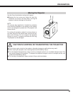
This projector adopts micro
computer to control the
appliance. The micro computer
rarely work incorrectly and may
not control the projector
properly. In that case, press
RESET button with sharpened
tool (like pen) to shut down the
appliance. The projector is
switched off.
D o not use RESET button
unreasonably.
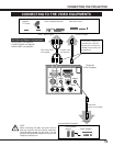
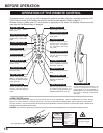
COMPUTER INPUT TERMINAL MONITOR OUTPUT TERMINAL
CONTROL PORT CONNECTOR
COMPUTER AUDIO INPUT JACK
AUDIO INPUT JACKS
VIDEO INPUT JACK
MCI SERIAL TERMINAL
AUDIO OUTPUT JACK
S-VIDEO INPUT JACK
RESET BUTTON
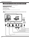
COMPUTER INPUT / MONITOR OUTPUT TERMINAL
Terminal : HDB15-PIN
Connect the display output terminal of the
computer to COMPUTER INPUT with the
VGA Cable (supplied). And connect the
monitor to MONITOR OUTPUT with the
monitor cable (not supplied). When
connecting the Macintosh computer, the
MAC/VGA Adapter is required.
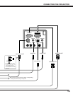
Terminal : MULTI-POLE 12-PIN
When controlling the computer with the
projector's Wireless Remote Control Unit,
connect control port (PS/2, Serial or ADB
port) on your computer to this terminal.
(Three types of cables are supplied.)
5
1
2
34
10
9 678
15
14 13
1112
1
2
3
4
5
6
7
8
9
10
11
12
Red Input
Ground (Horiz.sync.)
Green Input
Sense 2
Blue Input
Ground (Red)
Ground (Green)
Ground (Blue)
1
5
2
4
3
6
7
8
Non Connect
Horiz. sync.
Ground (Vert.sync.)
Sense 1
Sense 0
Vert. sync.
Reserved
9
13
10
12
11
14
15
-----
CLK
DATA
-----
-----
-----
-----
-----
GND
-----
-----
-----
T X D
-----
-----
-----
R X D
-----
READY
-----
GND
-----
-----
-----
-----
ADB
-----
-----
-----
-----
-----
-----
GND
-----
-----
-----
PS/2 Serial ADB
1
2
3
4
5
6
7
8
9
10
11
12
Pin Configuration
Pin Configuration
CONTROL PORT CONNECTOR