10
Model X-34 Owner’s Manual
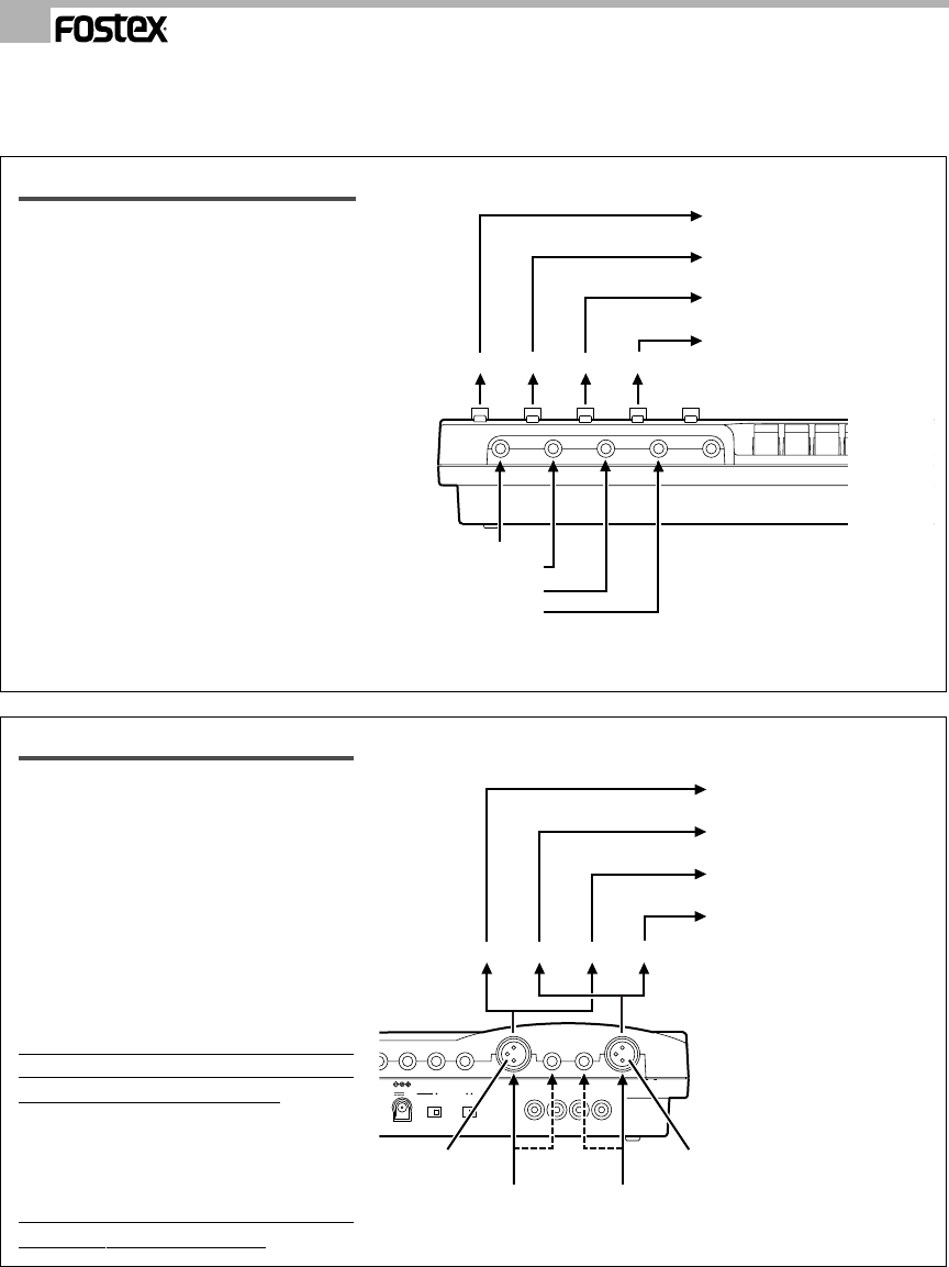
Front panel LINE IN/INSERT jack
Normally, a line level sound source with a
1/4" type plug is connected here. (You
cannot plug in a microphone here.).
Signals applied to each input jack are
recorded on the track selected by the
corresponding REC TRK switch.
Therefore, by connecting four different
sound sources to these LINE IN/INSERT
jacks, you can record up to four tracks
simultaneously.
These jacks can also serve as an insert
point. For example, you can connect
various effects here, such as a compressor
for a mic input to a rear panel jack.
These jacks are used as insert points only
for sound sources input to the rear panel
(jack or XLR).
For information on connecting effects, refer
to page 25.
Rear panel MIC IN (1/3, 2/4) jack
Microphones are generally plugged in
here.
Use the trim knob provided for each input
to adjust the input level to match the output
level of the connected sound source.
The Trim knobs attenuate the input level
to accommodate inputs ranging from mic
to line level.
Both 1/4" jacks and XLR connectors are
provided, allowing for many types of sound
sources.
However, remember that priority is given
to the 1/4" jack. If it is being used, the
XLR connectors are ineffective.
Unlike the front panel input jacks, signals
input to MIC IN 1/3 will be routed to
channels 1 and 3 , and signals input to MIC
IN 2/4 will be routed to channels 2 and 4.
The REC TRK switch setting determines
which tracks will be recorded.
Sound source A
Sound source B
Sound source C
Sound source D
CHANNEL
1234
REC TRK switch
REC TRK switch
REC TRK switch
REC TRK switch
Sound source A on the track
specified by REC TRK switch 1
Sound source B on the track
specified by REC TRK switch 2
Sound source C on the track
specified by REC TRK switch 3
Sound source D on the track
specified by REC TRK switch 4
Remember the following before you start to record!
The X-34 includes jacks (or connectors) for musical instrument and mic inputs on the front and rear panels.
The functions of these input jacks (or connectors) are explained below:
12V
DC IN
ON STANDBY
OFF
ON
DOLBY NR
TAPE OUT
1234
Sound source A
MIC IN jack 2/4 MIC IN jack 1/3
Sound source B
CHANNEL
4321
REC TRK switch
REC TRK switch
REC TRK switch
REC TRK switch
or or
Sound source A on the track
specified by REC TRK switch 4
Sound source B on the track
specified by REC TRK switch 3
Sound source A on the track
specified by REC TRK switch 2
Sound source B on the track
specified by REC TRK switch 1


