


FastIron GS Compact Layer 2 Switch Hardware Installation Guide
3 - 10 © 2007 Foundry Networks, Inc. September 2007
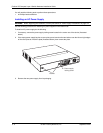
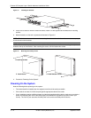
7. Press the two latches near the edges of the supply outward to lock the supply in place.
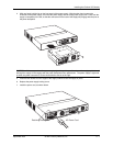
8. If you removed the receptacle for the positive and negative terminals, re-position it and secure the two screws.
9. Connect the ground, positive and negative wires as follows:
• Slip the ground wire into the opening under the marking until the wire is fully in place, then use the
crimper to crimp the lug snugly onto the wire. Gently pull the lug away from the wire to verify that the lug
is securely fastened.
• Connect the -48 VDC lead to the negative (—) terminal and tighten the negative terminal screw.
• Connect the 48 RTN lead to the positive (
+) terminal and tighten the positive terminal screw.
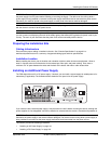
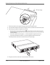
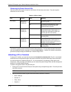
The following illustration shows how to connect the wires on a DC power supply.
10. Pull gently on each wire to make sure it is securely fastened in the connector.
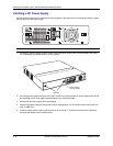
DC Power Supply
Plug on rear of
power supply
engages connector
Ground
+
–