


FastIron GS Compact Layer 2 Switch Hardware Installation Guide
6 - 4 © 2007 Foundry Networks, Inc. September 2007
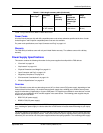
Power Source Interruptions
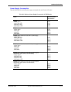
Table 6.4 shows how the FastIron GS protects against power surges and power drops.
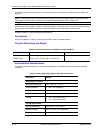
Mean Time Between Failure
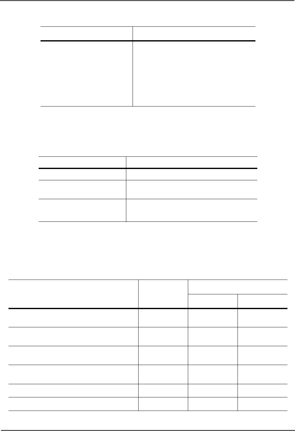
Table 6.5 lists the Mean Time Between Failure (MTBF) for the FastIron GS and the 10-GbE uplink modules. The
MTBF is the average estimated time, in units of hours, before a hardware failure may occur.
Safety EN 60950-1
CAN/CS-C22.2 No. 60950-1
EN 60825-1, Safety of Laser Products - Part 1
EN 60825-2, Safety of Laser Products - Part 2
IEC 60950-1
UL 60950-1
Table 6.4: Chassis Power Surge and Drop Protection
Property Protection Mechanism
Power surge MOV and Spark Gap protection
Power drop (<=1 second) An AC loss of >15ms will cause the power supply
to shut down due to input under-voltage
Maximum power draw 96 watts with 2-port 10-Gigabit uplinks
82 watts without 2-port 10-Gigabit uplinks
Table 6.5: MTBF for the FastIron GS and 10-GbE modules
Configuration / Module Temperature MTBF (hours)
Without POE With POE
24-port POE ready + 4 SFPs + 2-port 10-GbE
module + 2 XFPs + 1 power supply
40
o
Celsius
150,879 142,217
24-port POE ready + 4 SFPs + 2-port 10-GbE
module + 2 XFPs + 2 powers supplies
40
o
Celsius
267,411 241,356
48-port POE ready + 4 SFPs + 2-port 10-GbE
module + 2 XFPs + 1 power supply
40
o
Celsius
133,825 120,775
48-port POE ready + 4 SFPs + 2-port 10-GbE
module + 2 XFPs + 2 power supplies
40
o
Celsius
218,140 196,401
2-port 10-GbE XFP module
40
o
Celsius
1,597,580 N/A
2-port 10-GbE CX4 module
a
40
o
Celsius
29,673,590
Table 6.3: Chassis Regulatory Compliance (Continued)
Description Certifications