


Installing the FastIron GS Chassis
September 2007 © 2007 Foundry Networks, Inc. 3 - 17
• Flow control: None
When you establish the serial connection to the system, press Enter to display the CLI prompt in the terminal
emulation window. For example:
• FastIron>
• FastIron-PREM>
If you see one of these prompts, you are now connected to the system and can proceed to “Assigning Permanent
Passwords” on page 4-1.
You can customize the prompt by changing the system name. See the Foundry FastIron Configuration Guide.
If you do not see one of these prompts:
1. Make sure the cable is securely connected to your PC and to the Foundry system.
2. Check the settings in your terminal emulation program. In addition to the session settings listed above, make
sure the terminal emulation session is running on the same serial port you attached to the Foundry system.
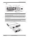
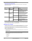
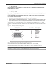
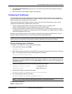
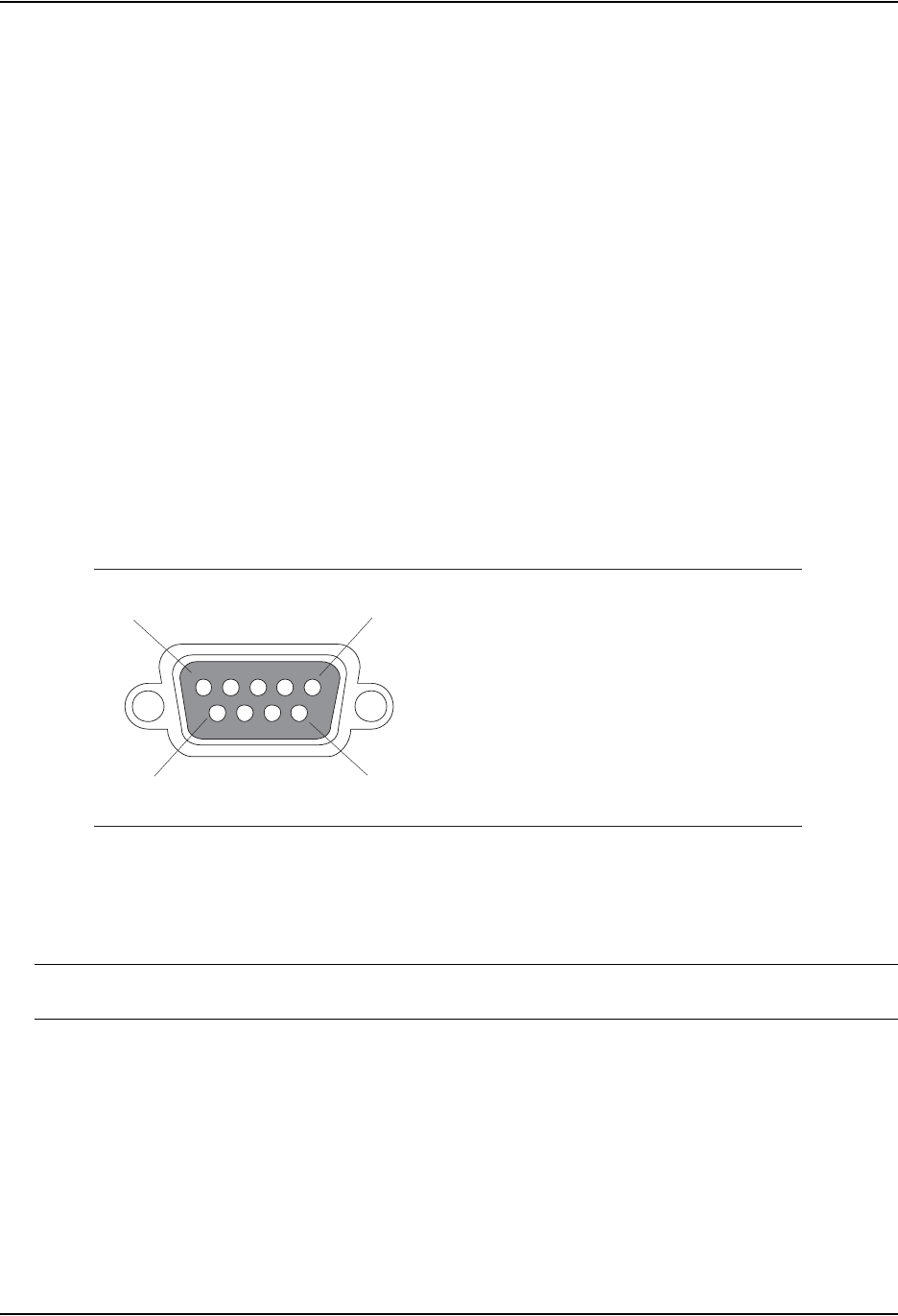
The EIA/TIA 232 serial communication port serves as a connection point for management by a PC or SNMP
workstation. Foundry switches and Layer 3 Switches come with a standard male DB-9 connector, shown in Figure
3.6.
Figure 3.6 Serial port pin and signalling details
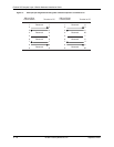
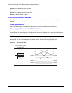
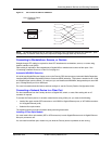
Most PC serial ports also require a cable with a female DB-9 connector.
Terminal connections will vary, requiring either a DB-9 or DB-25 connector, male or female.
Serial cable options between a Foundry switch or router and a PC or terminal are shown in Figure 3.7.
NOTE: As indicated in Figure 3.6 and Figure 3.7, some of the wires should not be connected. If you do connect
the wires that are labeled “Reserved”, you might get unexpected results with some terminals.
1
5
96
Pin Assignment
DB-9 male
Pin Number
1
2
3
4
5
6
7
8
9
Switch Signal
Reserved
TXD (output)
RXD (input)
GND
CTS (input)
RTS (output)
Reserved
Reserved
Reserved