


3 Unpacking and Installation
This chapter provides unpacking and installation information for the Switch.
3.1 Unpacking
Open the box and carefully unpacks its contents. The box should contain the following items:
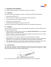
• One freeConnect Smart 2420
• One AC power cord, suitable for your area’s electrical power connections
• Four rubber feet to be used for shock cushioning
• Screws and two mounting brackets
• CD-ROM with Web Management Utility and User’s Guide
If any item is found missing or damaged, please contact your local reseller for replacement.
3.2 Installation
The site where you install the hub stack may greatly affect its performance. When installing the unit,
consider the following pointers:
• Install the Switch in a fairly cool and dry place. See Technical Specifications for the acceptable
temperature and humidity operating ranges.
• Install the Switch in a site free from strong electromagnetic field generators (such as motors),
vibration, dust, and direct exposure to sunlight.
• Leave at least 4” (10cm) of space at the front and rear of the Switch for ventilation.
• Install the Switch on a sturdy, level surface that can support its weight, or in an EIA standard-size
equipment rack. For information on rack installation, see the next section, Rack Mounting.
• When installing the Switch on a level surface, attach the rubber feet to the bottom of each device.
The rubber feet cushion the Switch and protect the case and surface from scratching.
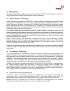
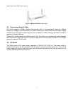
3.3 Rack Mounting
The Switch can be mounted in an EIA standard-size, 19-inch rack, which can be placed in a wiring
closet with other equipment. Attach the mounting brackets to the switch’s front panel (one on each
side), and secure them with the screws provided (Figure 1).
Figure 1: Attach the brackets to the Switch
Then, use the screws provided with the rack to mount each switch in the rack (Figure 2).