


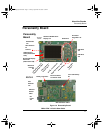
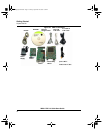
About the Boards
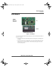
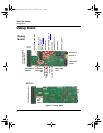
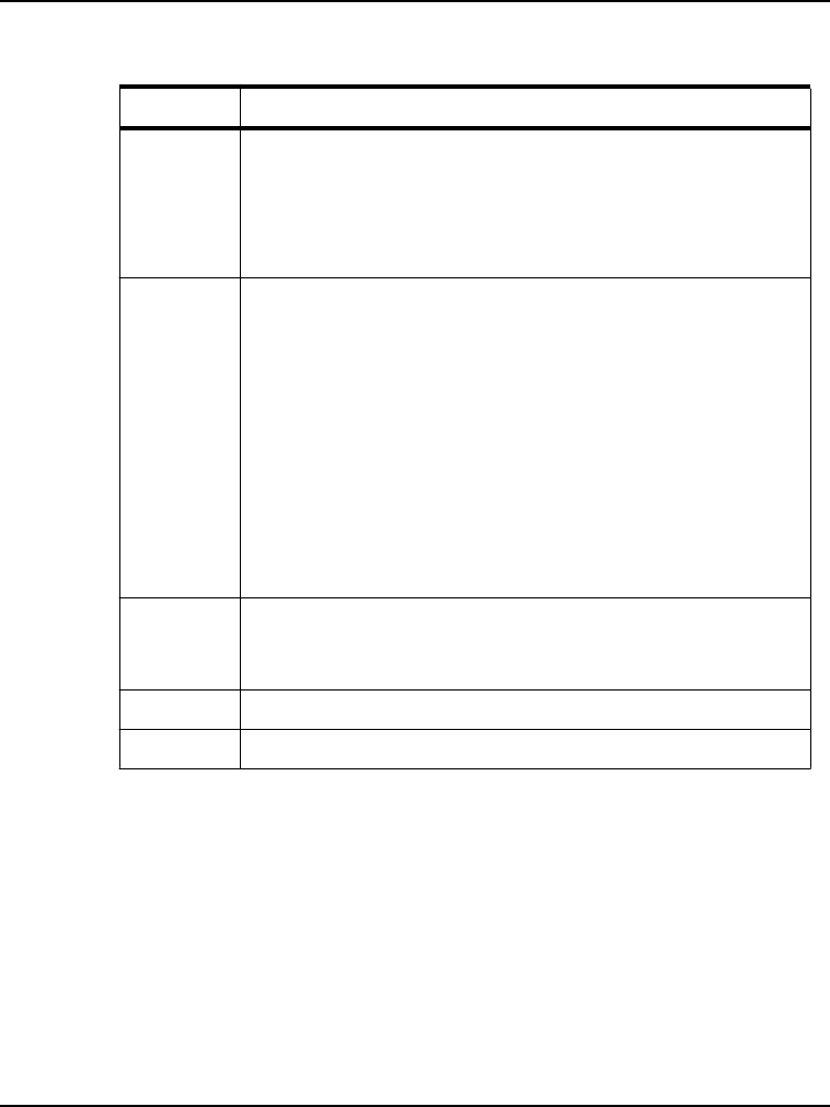
Debug Board
9
i.MX31 PDK 1.4 Quick Start Guide
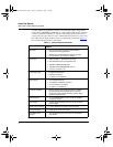
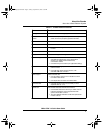
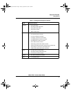
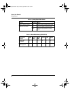
Table 1.2 Debug Board Physical Features
Type Physical Feature
Switches • S1: Power button
• S2: Debug board reset button
• S3: System reset switch
• S4: Power-on switch
• SW4: Enable switch
Connectors • J1:10/100 Base-T Ethernet RJ45 connector
• J2: 5.0V DC power connector
• J3: Current measure connector
• J4: 500-pin connector to CPU board
• P1: WEIM Address measure connector
• P2: WEIM Data measure connector
• CN1: i.MX31 JTAG connector
• CN2: Debug board CPLD JTAG connector
• CN3: Personality board CPLD JTAG connector (Reserved)
• CN74: 500-pin connector to Personality board
• CON4: UART (DCE) DB9 female connector
LEDs • D1–D8: LEDs for CPLD debug
• D9: LED for Debug board 3.3V power
• D11:LED for DC power supply
Buttons • BT1, BT2: Test buttons for CPLD
Fuse • F1: Resettable Fuse
3StackQS_WinCE.book Page 9 Sunday, September 28, 2008 1:58 PM