


2
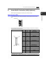
6. D-sub 25-Pin Connector (CN1) (Optional) 2-25
Specifications
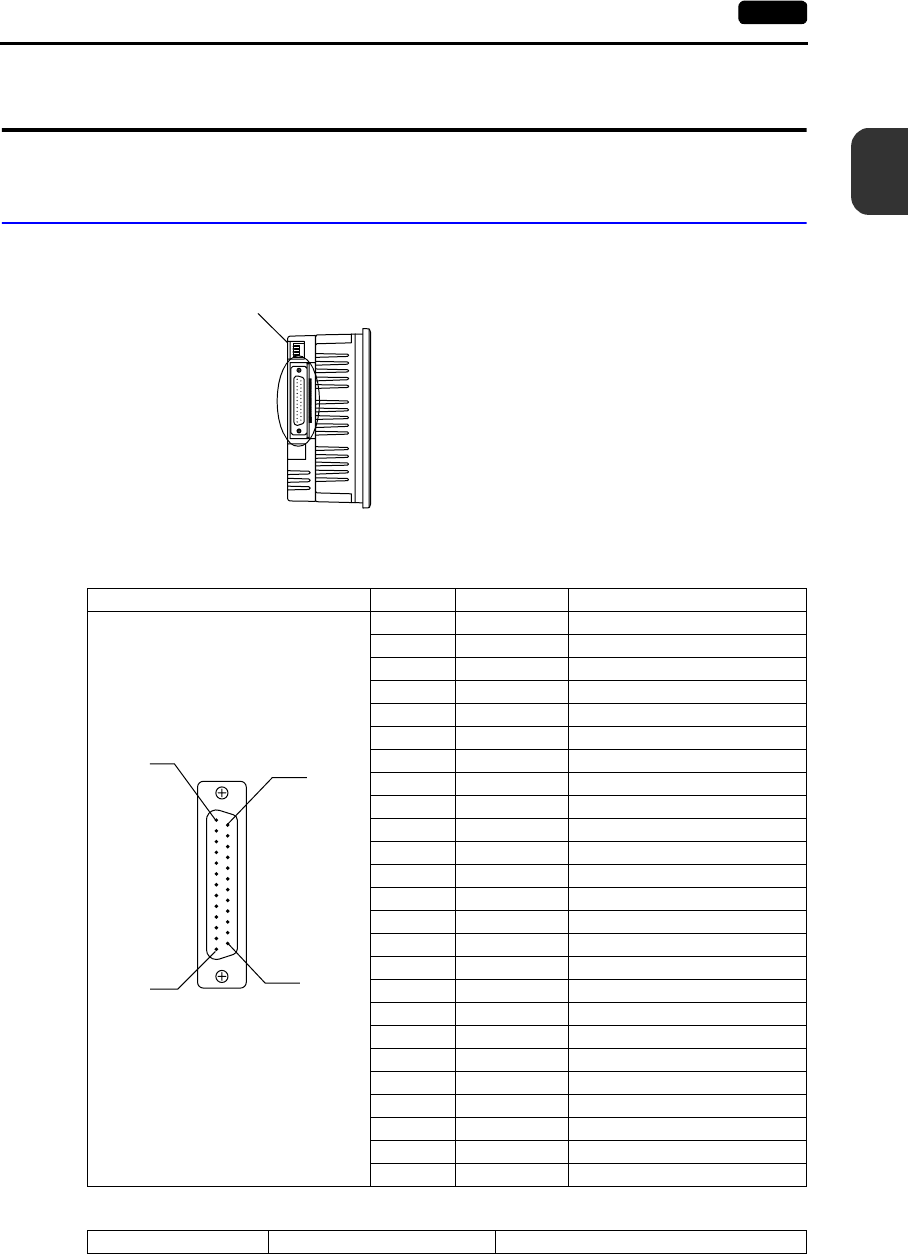
6. D-sub 25-Pin Connector (CN1) (Optional)
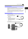
When the option unit UG230A-DCL is mounted, the CN1 connector is usable.
Serial Connector (CN1)
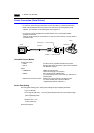
To communicate with the PLC (RS-232C, RS-422/485), connect the cable to the serial connector
(CN1).
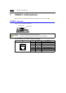
The correspondence between the serial connector pins and signals is shown below. The interface is
the same as that for the UG30-series CN1.
The following connector is recommended.
CN1 (D-sub 25-pin, female) Pin No. Signal Name Contents
1 FG Frame ground
2 SD RS-232C send data
3 RD RS-232C receive data
4 RS RS-232C RS request to send
5 CS RS-232C CS clear to send
6 Not used
7 SG Signal ground
8 Not used
9 +5V Use prohibited
10 0V Use prohibited
11 Not used
12 +SD RS-422 send data (+)
13 −SD RS-422 send data (−)
14 +RS RS-422 RS send data (+)
15 Not used
16 Not used
17 −RS RS-422 RS send data (−)
18 −CS RS-422 CS receive data (−)
19 +CS RS-422 CS receive data (+)
20 Not used
21 − Use prohibited
22 − Use prohibited
23 Not used
24 +RD RS-422 receive data (+)
25 −RD RS-422 receive data (−)
Recommended connector DDK-make 17JE23250-02 (D8A) D-sub 25-pin, male, metric thread, with hood
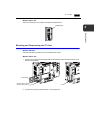
UG230A-DCL
1
14
13
25