


2
FBR12 SERIES
NOT FOR NEW
DESIGN
FBR12 SERIES TO
BE DISCONTINIED
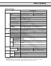
Life Mechanical 1 × 10
8
operations minimum
Electrical DC 2 × 10
5
operations minimum 5 × 10
5
operations minimum
(at contact rating)
AC 1 × 10
5
operations minimum 200 × 10
3
operations minimum
Other Vibration Misoperation 10 to 55 Hz (double amplitude of 3.3 mm)
Resistance
Endurance 10 to 55 Hz (double amplitude of 5.0 mm)
Shock Misoperation 500 m/s
2
(11±
1
ms)
Resistance
Endurance 1,000 m/s
2
( 6 ±
1
ms)
Weight Approx. 1.5 g Approx. 1.9 g Approx. 1.5 g Approx. 1.9 g
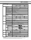
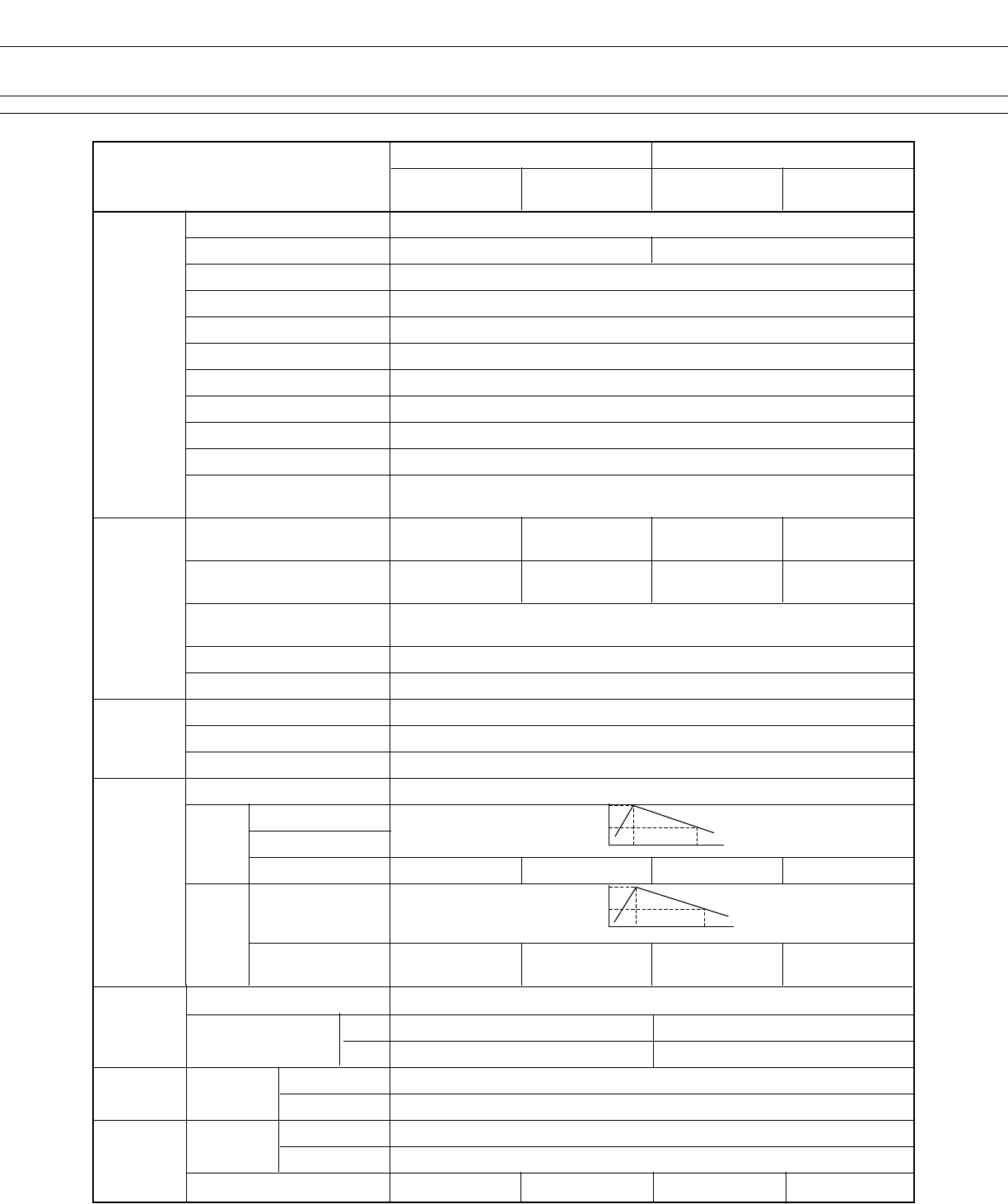
■ SPECIFICATIONS
Item
Standard (Gold-overlay silver-nickel)
-P type (Gold-overlay silver-palladium)
Standard
High dielectric
Standard
High dielectric
strength type strength type
Contact Arrangement 2 form C (DPDT)
Material Gold-overlay silver-nickel Gold-overlay silver-palladium
Style Bifurcated
Resistance (initial) Maximum 100 mΩ (at 0.1 A 6 VDC)
Rating (resistive) 0.5 A 125 VAC or 1 A 30 VDC
Maximum Carrying Current 2 A (at 20°C)
Maximum Switching Power 62.5 VA or 60 W
Max. Switching Voltage*
1
250 VAC or 220 VDC
Maximum Switching Current 2 A
Minimum Switching Load*
2
10 µA 10 VDC (reference)
Capacitance Approximately 1.0 pF (between open contacts, adjacent contacts )
(at 10 kHz) Approximately1.0 pF (between coil and contacts)
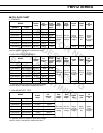
Coil Nominal power (at 20°C) Approximately Approximately Approximately Approximately
0.14 to 0.2 W 0.23 to 0.25 W 0.14 to 0.2 W 0.23 to 0.25 W
Operate power (at 20°C) Approximately Approximately Approximately Approximately
0.08 to 0.112 W 0.13 to 0.14 W 0.08 to 0.112 W 0.13 to 0.14 W
Thermal Resistance at
Approximately 115°C/W
Continuous Thermal Load
Operating Temperature –40°C to +85°C (no frost) (refer to the CHARACTERISTIC DATA)
Operating Humidity 45 to 85%RH
Time Value Operate (at nominal voltage) Maximum 4 msec.
Release (at nominal voltage) Maximum 4 msec.
Max. Switching Frequency Mechanical 3 Hz or electrical 0.5 Hz (at contact rating)
Insulation Resistance (initial) Minimum 1000 MΩ (at 500 VDC)
Dielectric
between open contacts
1,000 VAC
Strength
adjacent contacts
1 minimum
between coil and contacts
1,500 VAC 1 min. 2,000 VAC 1 min. 1,500 VAC 1 min. 2,000 VAC 1 min.
Surge
between open
1,500 V
Strength
contacts,
10 × 700 µs
adjacent contacts
between coil and contacts
2,500 V 5,000 V 2,500 V 5,000 V
2 × 10 µs 2 × 10 µs 2 × 10 µs 2 × 10 µs
1,500
750
10
700
2,500
1,250
210
*
1
If the switching voltage exceeds the rated contact voltage, reduce the current. The current values vary according to the
type of load.
*
2
Values when switching a resistive load at normal room temperature and humidity and in a clean environment.
The minimum switching load varies with the switching frequency and operation environment.