


5
FBR12 SERIES
NOT FOR NEW
DESIGN
FBR12 SERIES TO
BE DISCONTINIED
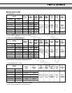
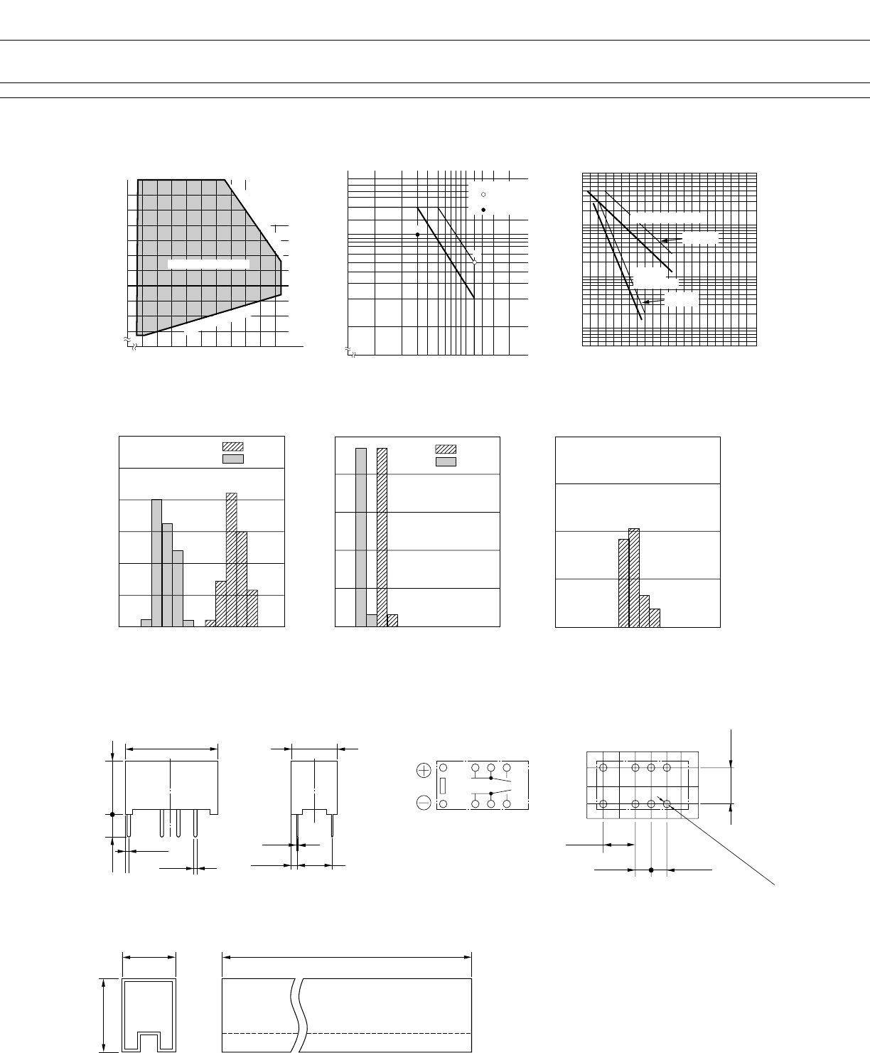
■ DIMENSIONS
Unit: mm
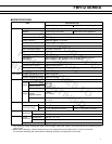
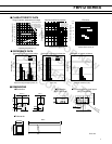
■ REFERENCE DATA
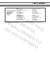
■ CHARACTERISTIC DATA
Life curve
500
Contact load current (A)
50
5
10
1
100
(×10
4
)
Service life (operations)
0.5 1.0 1.5 2.0
Maximum switching capacity
Contact load voltage (V)
0.1
10 20 125 200
30 50
0.2
0.3
0.5
1.0
2.0
➀
Range of operation temperature and voltage
Operating temperature (˚C)
–100 1020304050607080
70
80
90
100
110
120
130
140
150
160
➀ AC resistive load
( AC contact rating)
➁ DC resistive load
( DC contact rating)
Operating voltage range
Must operate voltage
Maximum allowable coil voltage
(DATA) assumes that
the maximum allow-
able temperature of
E type insulation
coil is 115˚C
➁
Contact load current (A)
Nominal voltage multiplying factor (%)
125 V AC
resistive load
30 V DC resistive load
(–P)TYPE
(–P)TYPE
●Dimensions ●Schematics
(BOTTOM VIEW)
●PC board mounting hole layout
(BOTTOM VIEW)
●Tube carrier
14.6
+0.4
0.50
(0.95)
9.7
+0.3
3.2
7.2
+0.3
0.25
(1.06) 5.08
1
12
3
10
4
9
5
8
5.08
2.54
5.08
2.54
8–ø1.00
10.6 Max.
30 pcs/Tube
15.6 Max.
500
±2
✽SHOW ONE OUT
OF THBSB 3 DIMENSIONS (See NA)
Operate
Release
Distribution of operate and release voltage
Rated coil voltage multiplying factor (%)
60
50
40
20
30
10
01020304050607080
0
Distribution (%)
Operate
Release
Distribution of operate and release time
Time (ms)
100
80
60
20
40
012345678
0
Contact resistance (mΩ)
Distribution of contact resistance
80
60
40
20
01020304050607080
0
Distribution (%)
Distribution (%)