


Change even page title here
Chapter 5 Configuration of the Evaluation-Board
UG-900001-32 - 10 - © Fujitsu Microelectronics Europe GmbH
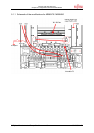
5 Configuration of the Evaluation-Board
The board is configured to work with the MB90F598 microcontroller.
In order to set up the board follow these steps:
1. disconnect power supply disconnected !
2. Set jumper JP1 to provide Vcc, i.e. 5V to the board
3. If case one is connecting this board to an emulator, it is recommended to set jumper JP2
in order to provide 3.7V to the internal core.
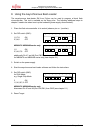
4. Please set the mode pins 1-3 on S3 according to your MCU operating mode. ON stands
for 0 and OFF for 1. E.g. MB90F598 all switches to OFF except no. 3.
5. Adjust both potentiometers (P1, P2) clockwise to their end position.
(Check that Pin 8 of U4 and Pin 8 of U5 are grounded.)
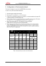
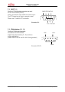
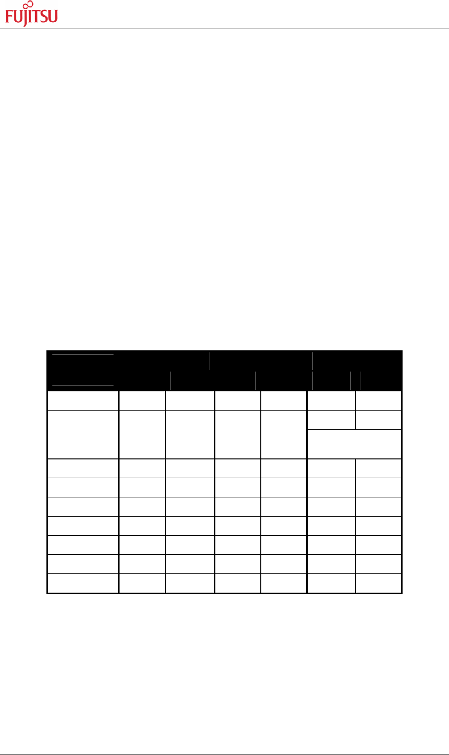
6. Select the appropriate CAN interface for the microcontroller you are using by setting
jumper JP3-JP6. Note that Pixx on the silk plot stands for Pinxx, i.e. the pin number.
E.g. for the MB90F598, set JP3 and JP4 to connect Pin 2 and 3 in order to connect to
MCU Pins 74 and 75, respectively.
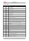
CAN0 CAN1 CAN2
Target
Series
RX0 TX0 RX1 TX1 RX2 TX2
MB90425 Pin 75 Pin 74 n.a. n.a. n.a. n.a.
Pin 72 Pin 71
MB90440 Pin 74 Pin 73 Pin 76 Pin 75
(Not supported by
Jumper 3-6 !)
MB90470 n.a. n.a. n.a. n.a. n.a. n.a.
MB90540 Pin 74 Pin 73 Pin 76 Pin 75 n.a. n.a.
MB90545 Pin 74 Pin 73 n.a. n.a. n.a. n.a.
MB90550 n.a. n.a. n.a. n.a. n.a. n.a.
MB90583 n.a. n.a. n.a. n.a. n.a. n.a.
MB90590 Pin 75 Pin 74 Pin 97 Pin 98 n.a. n.a.
MB90595 Pin 75 Pin 74 n.a. n.a. n.a. n.a.
Table 1: Microcontroller pin-number of the CAN-interface